WAFER-PV-D5252/D4252/N4552 SBC
Page 36
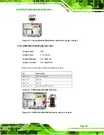
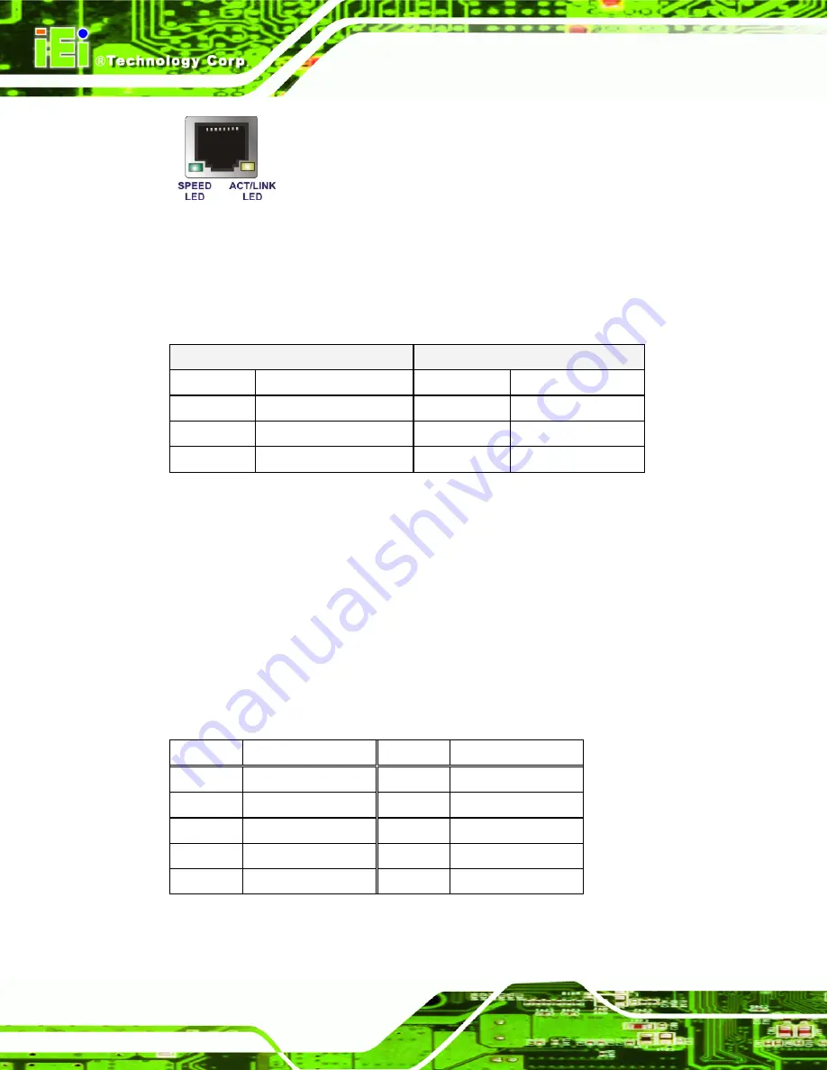
Figure 3-24: Ethernet Connector
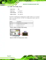
The RJ-45 Ethernet connector has two status LEDs, one green and one yellow. The green
LED indicates activity on the port and the yellow LED indicates the port is linked. See
.
SPEED LED
ACT/LINK LED
STATUS DESCRIPTION STATUS DESCRIPTION
OFF
10Mbps connection
OFF
No link
GREEN
100Mbps connection
YELLOW
Linked
ORANGE
1Gbps connection
BLINKING
Data Activity
Table 3-24: RJ-45 Ethernet Connector LEDs
3.3.2 Serial Port Connector
CN Label:
COM1
CN Type:
DB-9 Male connector
CN Location:
CN Pinouts:
The RS-232 serial connector provides serial connection in the RS-232 mode.
Pin Description Pin Description
1 DCD
6 DSR
2 RXD
7 RTS
3 TXD
8 CTS
4 DTR
9 RI
5 GND
Table 3-25: Serial Port Pinouts
Summary of Contents for WAFER-PV-D4252
Page 14: ...WAFER PV D5252 D4252 N4552 SBC Page 1 Chapter 1 1 Introduction...
Page 18: ...WAFER PV D5252 D4252 N4552 SBC Page 5 Figure 1 4 Dimensions with Heatsink mm...
Page 22: ...WAFER PV D5252 D4252 N4552 SBC Page 9 Chapter 2 2 Packing List...
Page 26: ...WAFER PV D5252 D4252 N4552 SBC Page 13 Chapter 3 3 Connector Pinouts...
Page 52: ...WAFER PV D5252 D4252 N4552 SBC Page 39 Chapter 4 4 Installation...
Page 76: ...WAFER PV D5252 D4252 N4552 SBC Page 63 Chapter 5 5 BIOS...
Page 104: ...WAFER PV D5252 D4252 N4552 SBC Page 91 Appendix A A BIOS Options...
Page 107: ...WAFER PV D5252 D4252 N4552 SBC Page 94 Appendix B B One Key Recovery...
Page 135: ...WAFER PV D5252 D4252 N4552 SBC Page 122 Appendix C C Terminology...
Page 139: ...WAFER PV D5252 D4252 N4552 SBC Page 126 Appendix D D Hazardous Materials Disclosure...

