IEI Technology VWBOX-122A User Manual Download Page 64


VWBOX-122A/133A Video Wall Controller 

Page 54 

A.1


Setup 

The serial port is used to remotely set and get the settings from the VWBOX-122A/133A. 

The  serial  port  is  used  by  user  applications  to  change  the  settings  of  the 

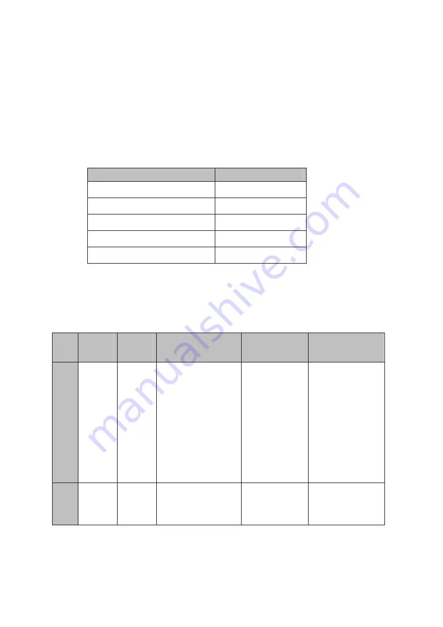
VWBOX-122A/133A  through  a  software  interface.  The  serial  port  should  be  setup  as 

indicated in Table 5-1 

Description 

Setting 

Baud rate 

115200 

Parity 

Non-parity 

Data bit 

Stop bit 

Flow control 

None 

Table 5-1: RS-232 Setup 

A.2


Command Reference 

The command reference format is shown in the table below. 

Type 

UART 

Opcode 

VCP 

Opcode 

Opcode Names 

High Byte 

Low Byte 

R/W 

0xB2 

Border Control 

0 – parent 

1 – child 1 

2 – child 2 

3 – child 3 

4 – child 4 

(2-7 only for sync) 

0 – off 

1 – on 

2 – MR 

3 – ML 

4 – MUL 

5 – MUR 

6 – MLL 

7 - MLR 

R/W 

0xE9 

Border X 

same as 0xB2 

set border X value 

0-16 – 122A/133A 

0-99 – E122/E133 

Summary of Contents for VWBOX-122A

Page 1: ...VWBOX 122A 133A Video Wall Controller Page 1 MODEL VWBOX UD133 Video Wall Controller Supports 2x2 and 3x3 LCD Panel Array Rev 1 01 12 August 2011 User Manual...

Page 2: ...VWBOX 122A 133A Video Wall Controller Page 2 Revision Date Version Changes 12 August 2011 1 01 Various changes 9 February 2009 1 00 Initial release...

Page 3: ...damages arising out of the use or inability to use the product or documentation even if advised of the possibility of such damages This document contains proprietary information protected by copyright...

Page 4: ...6 1 VWBOX 122A Dimensions 6 1 6 2 VWBOX 133A Dimensions 7 2 UNPACKING LIST 8 2 1 ANTI STATIC PRECAUTIONS 9 2 2 PACKING LIST 9 2 3 OPTIONAL ITEMS 10 3 INSTALLATION 11 3 1 REQUIREMENTS 12 3 1 1 Video Ca...

Page 5: ...23 4 OSD FUNCTIONS 24 4 1 ONSCREEN OSD 25 4 1 1 OSD Buttons 25 4 1 2 System Reset 25 4 1 3 OSD Menu 26 4 1 3 1 Mask Control 27 4 1 3 2 Link Control 28 4 1 3 3 Slave Mask Setting 29 4 1 3 4 Settings 3...

Page 6: ...ck Source Video Connection 52 A RS 232 SETUP 53 A 1 SETUP 54 A 2 PACKET FORMAT A 3 COMMAND REFERENCE A 3 1 Get Display Status A 3 2 Get Factory Defaults A 3 3 Set Mask Control A 3 4 Set Display Mode A...

Page 7: ...gure 3 5 VWBOX 133A Display Mode 20 Figure 3 6 Video Card Output Resolution 22 Figure 3 7 Don t Hide Display Modes 23 Figure 4 1 OSD Buttons 25 Figure 4 2 Reset to Factory Defaults 26 Figure 4 3 Mask...

Page 8: ...Tasks Figure 4 19 smartOSD Ready to Install Figure 4 20 smartOSD Installing Figure 4 21 smartOSD Installation Complete 39 Figure 4 22 smartOSD PC Setting 41 Figure 4 23 smartOSD Master Control Panel...

Page 9: ...3 VWBOX 133A Input and Output Resolution 21 Table 4 1 OSD Menu Structure 27 Table 4 2 smartOSD Menu Structure 40 Table 5 1 RS 232 Setup 54 Table 5 2 n Byte Data Output Format 60 Table 5 3 Get Display...

Page 10: ......

Page 11: ...VWBOX 122A 133A Video Wall Controller Page 1 Chapter 1 1 Introduction...

Page 12: ...ller accepts a single DVI input which is split over all the monitors in the array 1 2 Benefits The benefits of the VWBOX 122A 133A include Accurate high definition image Silent operation Simple setup...

Page 13: ...tches and LEDs This section gives and overview of the connectors switches and indicators on the VWBOX 122A 133A 1 4 1 Front Panel The front panel has the following buttons and indicators Power indicat...

Page 14: ...ators Multiple DVI video outputs o VWBOX 122A 4 x DVI output o VWBOX 133A 9 x DVI output 1 x DVI video input 1 x Power input 1 x Power switch 1x Sync in 1 x Sync out Figure 1 4 Rear Panel Figure 1 5 R...

Page 15: ...H VWBOX 122A 230 mm x 180 mm x 47 mm VWBOX 133A 295 mm x 188 mm x 47 mm Cooling Fanless Input Resolution See Section 3 6 Resolution and Display Mode Charts Output Resolution See Section 3 6 Resolution...

Page 16: ...3A Video Wall Controller Page 6 1 6 Dimensions This section gives the dimensions of the VWBOX 122A and VWBOX 133A 1 6 1 VWBOX 122A Dimensions Height 47 mm Width 230 mm Depth 180 mm Figure 1 6 VWBOX 12...

Page 17: ...VWBOX 122A 133A Video Wall Controller Page 7 1 6 2 VWBOX 133A Dimensions Height 47 mm Width 295 mm Depth 188 mm Figure 1 7 VWBOX 133A Dimensions...

Page 18: ...VWBOX 122A 133A Video Wall Controller Page 8 Chapter 2 2 Unpacking List...

Page 19: ...o the VWBOX 122A 133A does not fall out of the box Make sure all the components shown in Section 2 2 are present 2 2 Packing List NOTE If any parts are missing stop the installation and contact an IEI...

Page 20: ...age 10 No Description Image 1 User manual CD 1 DVI cable Table 2 1 Package List Contents 2 3 Optional Items The following optional items are available for the VWBOX 122A 133A No Description Image 1 DV...

Page 21: ...VWBOX 122A 133A Video Wall Controller Page 11 Chapter 3 3 Installation...

Page 22: ...000 series or higher ATI Radeon HD 3800 4600 series or higher Other graphics cards might work but must meet the requirements listed in Section 3 6 3 1 2 Monitors The monitors attached to the video box...

Page 23: ...ubsections below Dark black sections indicate the panels for the installation and the bold number indicate which video output 3 2 1 VWBOX 122A To setup the VWBOX 122A connect the monitors as shown bel...

Page 24: ...3x3 monitor setup on the VWBOX 133A connect the monitors as shown below 1 2 3 4 5 6 7 8 9 3 3 Install LCD Panels The monitors should be installed in one of the configurations shown in the previous se...

Page 25: ...rm surface Away from moisture and liquids Figure 3 1 Mounting Brackets 3 5 Connect Cables The cables that need to be attached are listed below Video input cable from the video source or computer eithe...

Page 26: ...tup Options Step 0 Figure 3 2 VWBOX 122A 133A Video Input 3 5 1 1 DVI Connector Specifications CN Label DVI1 CN Type DVI connector CN Pinouts See Table 3 1 The 24 pin Digital Visual Interface DVI conn...

Page 27: ...A 133A Optional The VWBOX 122A 133A has a male DB 9 connector on the rear panel The RS 232 cable connects to a computer that has the smartOSD software installed This enables the computer to control th...

Page 28: ...nector S t e p 0 3 5 3 Connect the VWBOX 122A 133A to the Power Supply Connect the included PSU into an AC power supply then connect the PSU to the VWBOX 122A 133A Turn the VWBOX 122A 133A on using th...

Page 29: ...A Display Mode Mode Input Resolution Output Resolution Vertical Hz Horizontal Hz Monitor Ratio Notes 1x1 1024x768 1024x768 60 48 36 4 3 2x1 2560x1024 1280x1024 60 63 98 5 4 3840x1080 1920x1080 50 56 2...

Page 30: ...0 54 27 92 Slave to VWBOX 122A Table 3 2 VWBOX 122A Input and Output Resolution 3 6 2 VWBOX 133A Figure 3 5 VWBOX 133A Display Mode Mode Input Resolution Output Resolution Vertical Hz Horizontal Hz Mo...

Page 31: ...cs card and on the video box follow the instructions below Step 1 Turn on the video box Step 2 Turn on the computer Step 3 The computer will automatically detect the video box Step 4 Set the required...

Page 32: ...2 After restarting check the output resolution Right click on the desktop and select Properties Figure 3 6 Video Card Output Resolution Step 3 Select the Advanced video card setting Step 4 Uncheck Hid...

Page 33: ...ezel compensation setting compensates for the gaps between monitors in the video wall array The bezel compensation sizes the image slightly larger than the visible screen to make the images on adjacen...

Page 34: ...VWBOX 122A 133A Video Wall Controller Page 24 Chapter 4 4 OSD Functions...

Page 35: ...re 4 1 OSD Buttons Menu Enter Enters the OSD selects items and sets the new values entered Left Moves the selection left Right Moves the selection right Up Moves the selection up Down Moves the select...

Page 36: ...LINK Toggles the link between the master video box s mask value and the slave s value SCAN Toggles the scan function for detecting the attached slave video boxes Slave Mask Setting DVI DVI 1 4 Settin...

Page 37: ...ync and Power SYNC For debugging Power Turns the power on and off Version Information FPGA Version number of one FPGA chip CPLD Version number of the CPLD chip FW Firmware version number Model informa...

Page 38: ...s in the video wall Off On X Adjusts the amount of compensation from left to right Y Adjusts the amount of compensation from top to bottom 4 1 3 2 Link Control Link control allows the master controlle...

Page 39: ...This setting indicates which slaves settings are shown DVI 1 4 Mask link is on and all slaves have the same setting DVI 1 Mask link is off The first video box s settings are shown DVI 2 Mask link is o...

Page 40: ...ve monitors Figure 4 6 Settings OUT This setting is the output resolution from the video box MODE This setting shows the video output mode of the video box VW 2x2 video mode on the VWBOX 122A S 2x1 vi...

Page 41: ...output resolution on the computer should be adjusted to the shown value Figure 4 7 Warning Change Setting Shows the value that the computer video output should be set to 4 1 3 6 Information The inform...

Page 42: ...3 7 Slave Video Box Output The slave video box output setting shows the output resolution from the slave video box Figure 4 9 Slave Video Box Output DS Indicates which video box slave settings are sh...

Page 43: ...c and power menu toggles sync and turns the power on and off Figure 4 10 Sync and Power SYNC For debugging POWER Turns the power off 4 1 3 9 Firmware Information The firmware information screen shows...

Page 44: ...l Number The serial number page shows the model name and serial number of the video box Figure 4 12 Serial Number Model Name The first line displays the video box s model name SN This displays the vid...

Page 45: ...mote Control Power Turns the video box on and off Menu Enters the OSD selects items and sets the new values entered Left Moves the selection left Right Moves the selection right Up Moves the selection...

Page 46: ...ons when adjusting a monitor smartOSD also allows the screen output screen resolution and mask size to be adjusted over a DVI cable The smartOSD can compatible with the following operating systems Win...

Page 47: ...ontroller Page 37 Step 3 Installation starts automatically Figure 4 14 Figure 4 14 Preparing to Install Step 4 The welcome screen shown below appears Figure 4 15 Figure 4 15 smartOSD Welcome Screen St...

Page 48: ...er Page 38 Step 6 Installation is ready to begin Figure 4 16 Figure 4 16 Ready to Install Step 7 Click INSTALL to continue the installation Step 8 The installation progress bar appears Figure 4 17 Fig...

Page 49: ...A 133A Video Wall Controller Page 39 Step 9 When the installation is complete the screen below appears Figure 4 18 smartOSD Installation Complete Step 10 Click FINISH to close the installation wizard...

Page 50: ...ng Interface Selection Master Control Panel Mask Control Display Resolution Display Mode Mask Setting Slave Control Panel Selection Mask Selection Mask Settings Master VWBOX Data Mask On Off Mask X Ma...

Page 51: ...communication between the video box and the computer Figure 4 19 smartOSD PC Setting DVI Selects the DVI input signal Identify The Identify button shows a red square for each full image in the array...

Page 52: ...rol Panel Mask Control The Mask Control options allow the images to be adjusted to compensate for the gaps between monitors in the video array Off The images are shown without any adjustments On The v...

Page 53: ...ght video box in a four video box setup MLL The lower left corner is fixed and the upper right corner position changes when adjustments are made for lower left video box in a four video box setup MLR...

Page 54: ...44 1280 x 960 1280 x 1024 1360 x 768 1696 x 960 1920 x 1080 1920 x 1200 1920 x 1440 Display Mode The display mode sets the output mode of the video box as shown in Section 3 6 Resolution and Display...

Page 55: ...e master and slaves DVI Connection Mode DVI connection mode selects what is connected to the output of the master video box DVI Child Number Sets the video output to set Mask Control The Mask Control...

Page 56: ...e lower right corner position changes when adjustments are made for top left video box in a four video box setup MUR The upper right corner is fixed and the lower left corner position changes when adj...

Page 57: ...VWBOX 122A 133A Video Wall Controller Page 47 4 2 2 4 Master Data The Master Data menu displays the current settings of the master video wall box Figure 4 22 smartOSD Master Data...

Page 58: ...VWBOX 122A 133A Video Wall Controller Page 48 4 2 2 5 About Page The About Page shows some general information about the smartOSD Figure 4 23 smartOSD About Page...

Page 59: ...VWBOX 122A 133A Video Wall Controller Page 49 Chapter 5 5 Troubleshooting and Maintenance...

Page 60: ...are strictly adhered to Wear an anti static wristband Wearing a simple anti static wristband can help to prevent ESD from damaging the board Use an anti static pad When configuring the VWBOX 122A 133A...

Page 61: ...y fastened to the monitor and to the power source S t e p 0 5 3 1 2 Check Monitor Video Connection Check to see that the video cable is fitted correctly Step 1 Check that the monitor is connected to t...

Page 62: ...ource Step 2 Check that the VWBOX 122A 133A is connected to the power supply S t e p 0 5 3 3 2 Check Source Video Connection Check to that the source video cable is securely connected to the VWBOX 122...

Page 63: ...VWBOX 122A 133A Video Wall Controller Page 53 Appendix A A RS 232 Setup...

Page 64: ...ndicated in Table 5 1 Description Setting Baud rate 115200 Parity Non parity Data bit 8 Stop bit 1 Flow control None Table 5 1 RS 232 Setup A 2 Command Reference The command reference format is shown...

Page 65: ...E122 E133 R W D 0xB0 Output Display Resolution Empty No child 0 640x480 1 848x480 2 1024x768 3 1280x720 4 1280x800 5 1280x960 6 1280x1024 7 1360x768 8 1696x960 9 1920x1080 10 1920x1200 11 1920x1440 Ch...

Page 66: ...off 1 link off R F 0xE3 Input Resolution Empty 0 15 as per figure 16 invalid 17 no signal R L 0xF8 Model ID Empty 0 E122 1 E133 2 122A 3 133A R J 0xE4 FPGA ver Ver no high byte Ver no low byte R I 0xE...

Page 67: ...0xEF EDID select Empty 0 XGA 1 SXGA 2 HDTV 3 WUXGA R W S 0xF0 Scan DVI output Empty 0 OFF 1 ON Table 5 2 VWBOX 122A Command Reference Type UART Opcode VCP Opcode Opcode Names High Byte Low Byte R W A...

Page 68: ...D 0xB0 Output Display Resolution Empty Write 0 640x480 1 1024x768 2 1280x720 3 1280x800 4 1280x960 5 1280x1024 6 1360x768 Read With 122A as child 0 640x480 1 1024x768 2 1280x720 3 1280x800 4 1280x960...

Page 69: ...3 Input Resolution Empty 0 15 as per figure 16 invalid 17 no signal R L 0xF8 Model ID Empty 0 E122 1 E133 2 122A 3 133A R J 0xE4 FPGA ver Ver no high byte Ver no low byte R I 0xE5 CPLD ver Ver no high...

Page 70: ...0xEF EDID select Empty 0 XGA 1 SXGA 2 HDTV 3 WUXGA R W S 0xF0 Scan DVI output Empty 0 OFF 1 ON Table 5 3 VWBOX 133A Command Reference Byte Function 1 The number of bytes in the signal 2 This byte indi...

Page 71: ...VWBOX 122A 133A Video Wall Controller Page 61 Appendix B B DDC2BI Setup...

Page 72: ...l machines to read and write settings to the VWBOX 122A 133A Type UART Opcode VCP Opcode Opcode Names High Byte Low Byte R W A 0xB2 Border Control 0 parent 1 child 1 2 child 2 3 child 3 4 child 4 2 7...

Page 73: ...6x960 9 1920x1080 10 1920x1200 11 1920x1440 R W N 0xB1 Output Display Mode Empty 0 2x2 1 2x1 1x1 R W E 0xE0 Sync Empty 0 Sync off 1 Sync on W F 0xE1 Connect Message Empty 1 connect message every 5 sec...

Page 74: ...Ver no low byte R K 0xED Serial number High word Low word W K 0xED Serial High word 0xEE number Low word R W O 0xE8 Output display resolution Empty 0 1024x768 1 1360x768 2 1280x1024 3 1400x1050 4 1680...

Page 75: ...VWBOX 122A 133A Video Wall Controller Page 65 Appendix C C Terminology...

Page 76: ...written to the selected address to enable the DIO functions DVI The Digital Video Interface standard allows analog and digital video transmission GPIO General purpose input output LCD Liquid crystal...

Page 77: ...VWBOX 122A 133A Video Wall Controller Page 67 Appendix D D Hazardous Materials Disclosure...

Page 78: ...ges the presences of small quantities of certain materials in the product and is applicable to China RoHS only A label will be placed on each product to indicate the estimated Environmentally Friendly...

Page 79: ...Circuit Board X O O O O X Metal Fasteners X O O O O O Cable Assembly X O O O O X Fan Assembly X O O O O X Power Supply Assemblies X O O O O X Battery O O O O O O O This toxic or hazardous substance i...

Page 80: ...122A 133A Video Wall Controller Page 70 RoHS RoHS Pb Hg Cd CR VI PBB PBDE X O O O O X X O O O O X X O O O O X X O O O O O X O O O O X X O O O O X X O O O O X O O O O O O O SJ T11363 2006 X SJ T11363...

Page 81: ...VWBOX 122A 133A Video Wall Controller Page 71 Index...

Page 82: ...static precautions 52 anti static pad 52 anti static wristband 52 D DVI connector 16 E electrostatic discharge 52 O OSD Remote Control 35 R Remote Contol 35 remote control 35 T troubleshooting 53 U un...

Reviews: