UPC-F12C-ULT3 Panel PC
Page 19
Use the RJ-45 to DB-9 serial port cable shipped with the UPC-F12C-ULT3 to connect to a
serial device. The pinouts of the RJ-45 to DB-9 serial port cable are listed below.
PIN NO.
RS-232
RS-422
RS-485
1
DCD
TXD422-
TXD485-
2
RXD
3
TXD
--
4
DTR
RXD422-
--
5
GND
--
--
6
DSR
--
--
7
RTS
--
--
8
CTS
--
--
9
RI
--
--
Table 3-3: DB-9 RS-232/422/485 Pinouts
3.4.3 Clear CMOS
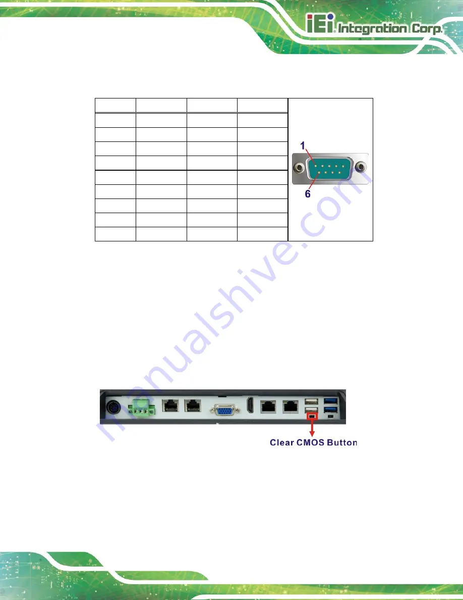
If the UPC-F12C-ULT3 fails to boot due to improper BIOS settings, the clear CMOS
jumper clears the CMOS data and resets the system BIOS information. To do this, push
the clear CMOS button for three seconds, then restart the system. The clear CMOS button
location is shown in
. The I/O cover must be removed to be able to access the
clear CMOS button.
Figure 3-5: Clear CMOS Button Location
Summary of Contents for UPC-F12C-ULT3
Page 15: ...UPC F12C ULT3 Panel PC Page 1 1 Introduction Chapter 1 ...
Page 23: ...UPC F12C ULT3 Panel PC Page 9 2 Unpacking Chapter 2 ...
Page 27: ...UPC F12C ULT3 Panel PC Page 13 3 Installation Chapter 3 ...
Page 43: ...UPC F12C ULT3 Panel PC Page 29 4 BIOS Setup Chapter 4 ...
Page 75: ...UPC F12C ULT3 Panel PC Page 61 Chapter 5 5 Interface Connectors ...
Page 95: ...UPC F12C ULT3 Panel PC Page 81 Appendix A A Regulatory Compliance ...
Page 100: ...UPC F12C ULT3 Panel PC Page 86 B Safety Precautions Appendix B ...
Page 106: ...UPC F12C ULT3 Panel PC Page 92 C BIOS Menu Options Appendix C ...
Page 109: ...UPC F12C ULT3 Panel PC Page 95 Appendix D D Watchdog Timer ...
Page 112: ...UPC F12C ULT3 Panel PC Page 98 Appendix E E Hazardous Materials Disclosure ...


