background image


TANK-6000-C226  Em b e d d e d   S ys te m  

P a g e   22 

To install these devices, connect the corresponding cable connector from the actual 

device to the corresponding TANK-6000-C226  external peripheral interface connector 

making sure the pins are properly aligned. 

3.8.1


Au d io   Co n n e c tio n  

The audio jacks on the external audio connector enable the TANK-6000-C226  to be 

connected to a stereo sound setup. To install the audio devices, follow the steps below. 

S te p  1:


Identify the audio plugs

. The plugs on your home theater system or speakers 

may not match the colors on the rear panel. If audio plugs are plugged into the 

wrong jacks, sound quality will be very bad. 

S te p  2:


Plug the audio plugs into the audio jacks

. Plug the audio plugs into the audio 

jacks. If the plugs on your speakers are different, an adapter will need to be used 

to plug them into the audio jacks. 


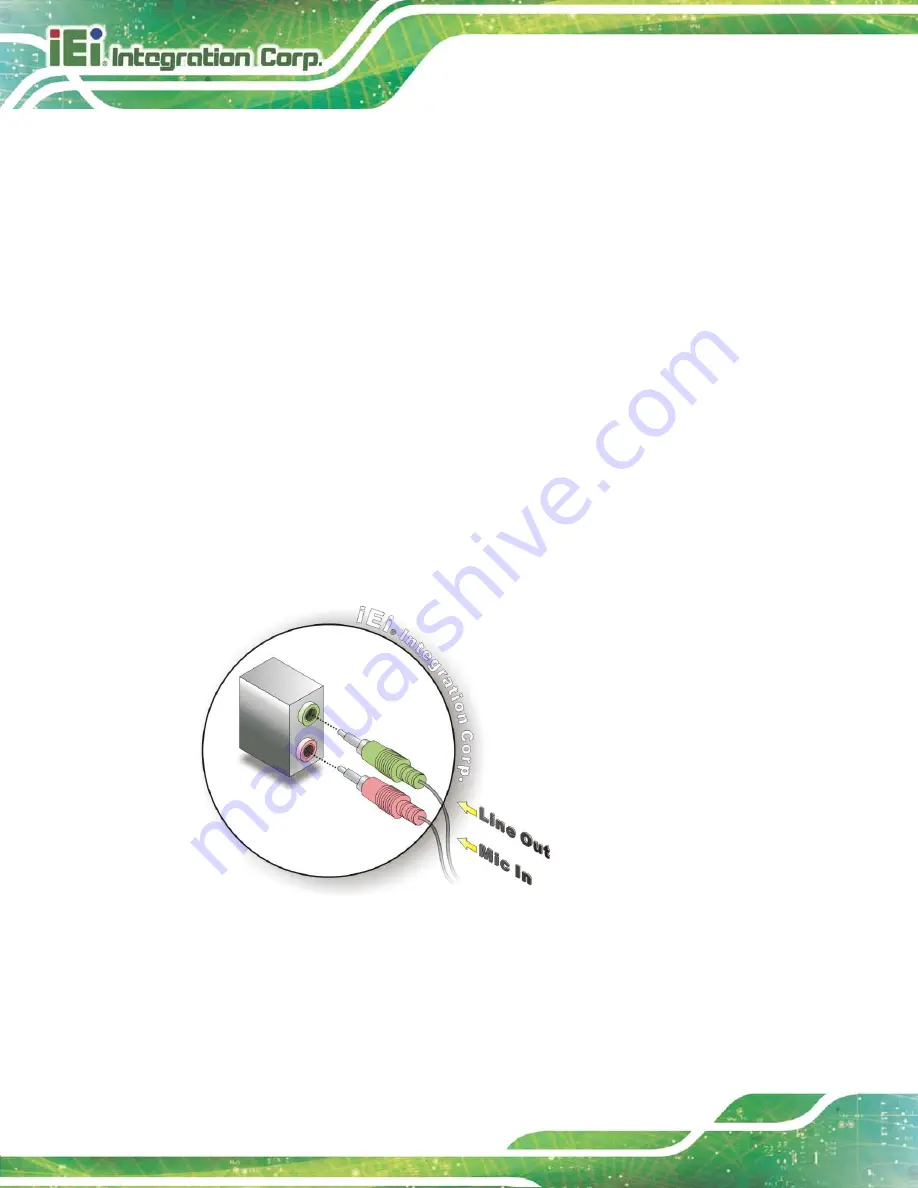
Line Out port (Lime): 

Connects to a headphone or a speaker. 


Microphone (Pink): 

Connects to a microphone. 


Figure 3-13: Audio Connector 

S te p  3:


Check audio clarity

. Check that the sound is coming through the right speakers 

by adjusting the balance front to rear and left to right.


Summary of Contents for TANK-6000-C226i-E3/4G-R10

Page 1: ...Embedded Sys tem Page i Us er Manual MODEL TANK 6000 C226 Embedded s ys tem s upports 22nm LGA1155 Intel Xeon E3 Core i3 CPU HDMI VGA GbE Two USB 2 0 Four USB 3 0 Two COM and RoHS Compliant Rev 1 00...

Page 2: ...TANK 6000 C226 Embedded Sys tem Page ii Revis ion Date Version Changes 14 March 2014 1 00 Initial release...

Page 3: ...mages arising out of the use or inability to use the product or documentation even if advised of the possibility of such damages This document contains proprietary information protected by copyright A...

Page 4: ...CAUTIONS 13 3 2 INSTALLATION AND CONFIGURATION STEPS 13 3 3 HARD DISK DRIVE HDD INSTALLATION 14 3 3 1 Serial ATA 2 0 Drive Installation 14 3 3 2 Serial ATA 3 0 Drive Installation 16 3 4 PCIE EXPANSION...

Page 5: ...PI1 33 4 2 9 OLED Connector OLED1 33 4 2 10 Power on Connector CN3 33 4 2 11 Serial ATA 3 0 connectors SATA1 34 4 3 EXTERNAL INTERFACE PANEL CONNECTORS 34 4 3 1 Audio Input Output Connectors MIC1 AUDI...

Page 6: ...55 5 3 9 iWDD H W Monitor 57 5 3 9 1 Smart Fan Mode Configuration 58 5 3 10 Serial Port Console Redirection 59 5 3 11 iEi Feature 62 5 4 CHIPSET 63 5 4 1 PCH IO Configuration 64 5 4 1 1 PCH Azalia Co...

Page 7: ...RECOVERY TOOL FUNCTIONS 109 C 5 1 Factory Restore 110 C 5 2 Backup System 111 C 5 3 Restore Your Last Backup 112 C 5 4 Manual 113 C 6 RESTORE SYSTEMS FROM A LINUX SERVER THROUGH LAN 114 C 6 1 Configur...

Page 8: ...w 18 Figure 3 9 Install PCIe Card 18 Figure 3 10 AT ATX Switch Location 19 Figure 3 11 Reset Button Location 20 Figure 3 12 Mounting Bracket Retention Screws 21 Figure 3 13 Audio Connector 22 Figure 3...

Page 9: ...101 Figure C 22 Auto Recovery Utility 102 Figure C 23 Launching the Recovery Tool 102 Figure C 24 Auto Recovery Environment for Windows 102 Figure C 25 Building the Auto Recovery Partition 103 Figure...

Page 10: ...nouts 33 Table 4 10 OLED Connector OLED1 Pinouts 33 Table 4 11 Power on Connector CN3 Pinouts 33 Table 4 12 Serial ATA 3 0 connectors SATA1 Pinouts 34 Table 4 13 Rear Panel Connectors 35 Table 4 14 Au...

Page 11: ...TANK 6000 C226 Embedded Sys tem Page 1 Chapter 1 1 Introduction...

Page 12: ...th up to 3 Gb s data transfer rate and two 2 5 SATA HDDs with up to 6 Gb s data transfer rate Two serial ports two external USB 2 0 ports and four external USB 3 0 ports ensure simplified connectivity...

Page 13: ...sfer Programmable OLED display RoHS compliant 1 4 Technical Specifications The TANK 6000 C226 technical specifications are listed in 331HTable 1 2 Chas s is Color Black Dimens ions WxHxD 310 mm x 199...

Page 14: ...nsions PCIe 2 x PCIe by 8 Power Power Supply 19V 24V DC Reliability Mounting Wall mount Operating Temperature 20 C 55 C with air flow SSD Operating Humidity 10 90 non condensing Operating Shock Half s...

Page 15: ...has the following features Figure 1 3 1 x 4 pin power jack for 19V 24V power input 1 x 4 pin terminal block for 19V 24V power input 1 x AT ATX Switch 1 x HDMI port 1 x Line out port green 1 x Mic in p...

Page 16: ...TANK 6000 C226 Embedded Sys tem Page 6 Figure 1 3 TANK 6000 C226 Rear Panel...

Page 17: ...TANK 6000 C226 Embedded Sys tem Page 7 1 7 Dimens ions The physical dimensions are shown below Figure 1 4 Physical Dimensions mm...

Page 18: ...TANK 6000 C226 Embedded Sys tem Page 8 Chapter 2 2 Unpacking...

Page 19: ...istband Wearing a simple anti static wristband can help to prevent ESD from damaging the board Self grounding Before handling the board touch any grounded conducting material During the time the board...

Page 20: ...purchased the TANK 6000 C226 from or contact an IEI sales representative directly To contact an IEI sales representative please send an email to 165Hsales iei com tw The TANK 6000 C226 is shipped with...

Page 21: ...TANK 6000 C226 Embedded Sys tem Page 11 Quantity Item and Part Number Image 1 Utility CD 1 One Key Recovery CD Table 2 1 Package List Contents...

Page 22: ...TANK 6000 C226 Embedded Sys tem Page 12 Chapter 3 3 Ins tallation...

Page 23: ...fied Personnel The TANK 6000 C226 must be installed and operated only by trained and qualified personnel Maintenance upgrades or repairs may only be carried out by qualified personnel who are familiar...

Page 24: ...ion To install the hard disk drive to the SATA 2 0 driver bay please follow the steps below Step 1 Remove two retention screws from the HDD cover as shown in 335HFigure 3 1 Figure 3 1 HDD Cover Retent...

Page 25: ...s Step 4 Lift the HDD bracket out of the TANK 6000 C226 and slide the HDD to the HDD bracket 336HFigure 3 3 Figure 3 3 Inserting the HDD Step 5 Install the HDD bracket in the same position it was befo...

Page 26: ...s below Step 1 Unlock the HDD drive bay using the key The keys can be found in the packing list Figure 3 4 HDD Drive Bay Step 2 Loosen two HDD bracket retention screws and lift the HDD bracket out of...

Page 27: ...the HDD bracket retention screws Step 5 Lock the HDD drive bay using the key 3 4 PCIe Expans ion Card Ins tallation Optional To install a PCIe expansion card please do the following Step 1 Loosen the...

Page 28: ...Screw Step 3 Insert the expansion card Align the PCIe expansion card edge connector with the PCIe expansion slot on the PCIe riser card Gently insert the PCIe card into the PCIe expansion slot Step 4...

Page 29: ...the AT mode selected the power is controlled by a central power unit rather than a power switch The TANK 6000 C226 panel PC turns on automatically when the power is connected The AT mode benefits a pr...

Page 30: ...ot the system when the system is turned on To reboot the system follow the steps below Step 1 Locate the reset button on the rear panel Figure 3 11 Figure 3 11 Reset Button Location Step 2 Press the r...

Page 31: ...e Step 5 Align the mounting holes in the sides of the mounting brackets with the predrilled holes in the mounting surface Step 6 Insert four retention screws two in each bracket to secure the system t...

Page 32: ...he audio plugs The plugs on your home theater system or speakers may not match the colors on the rear panel If audio plugs are plugged into the wrong jacks sound quality will be very bad Step 2 Plug t...

Page 33: ...ort Make sure the orientation of the connector is correct Figure 3 14 HDMI Connection Step 3 Insert the HDMI connector Gently insert the HDMI connector The connector should engage with a gentle push I...

Page 34: ...able RJ 45 connector Once aligned gently insert the LAN cable RJ 45 connector into the RJ 45 connector Step 0 3 8 4 DB 9 Serial Port Connection There are two RS 232 DB 9 connectors on the TANK 6000 C2...

Page 35: ...e connector Step 0 3 8 5 USB Device Connection NOTE User must install the USB 3 0 driver before connecting a USB device to the system or else the system may not recognize the connected device There ar...

Page 36: ...or 3 8 6 VGA Monitor Connection The TANK 6000 C226 has one female DB 15 connectors on the external peripheral interface panel The DB 15 connector is connected to a CRT or VGA monitor To connect a moni...

Page 37: ...the insert the male connector from the VGA screen into the female connector on the TANK 6000 C226 See Figure 3 19 Figure 3 18 VGA Connector Step 4 Secure the connector Secure the DB 15 VGA connector...

Page 38: ...TANK 6000 C226 Embedded Sys tem Page 28 Chapter 4 4 Sys tem Motherboard...

Page 39: ...h a number of peripheral interface connectors and configuration jumpers The connector locations are shown in Figure 6 1 The Pin 1 locations of the on board connectors are also indicated in the diagram...

Page 40: ...r connector 4 pin Molex CN1 Battery connector 2 pin wafer BAT1 BMC debug connector 4 pin wafer J2_BMC EC debug port connector 20 pin FPC connector CN2 Fan connectors 4 pin wafer CPU_FAN1 SYS_FAN2 Flas...

Page 41: ...TION PIN NO DESCRIPTION 1 EC_EPP_STB 2 EC_EPP_PD0 3 EC_EPP_PD1 4 EC_EPP_PD2 5 EC_EPP_PD3 6 EC_EPP_PD4 7 EC_EPP_PD5 8 EC_EPP_PD6 9 EC_EPP_PD7 10 NC 11 EC_EPP_BUSY 12 EC_EPP_KSI5 13 EC_EPP_KSI4 14 EC_EP...

Page 42: ...NO DESCRIPTION 1 GND 2 12V 3 FANIO 4 PWM Table 4 6 Fan Connectors CPU_FAN1 SYS_FAN2 Pinouts PIN NO DESCRIPTION 1 V3 3M_SPI_CON 2 SPI_CS 0_CN 3 SPI_SO_SW 3 SPI_CLK_SW 5 SPI_SI_SW 6 GND Table 4 7 Flash...

Page 43: ...NO DESCRIPTION 1 SPI_VCC 2 FLA_CS0_R 3 FLA_D2_R 3 FLA_D0_R 5 FLA_D1_R 6 GND Table 4 9 Flash BMC ROM Connector SPI1 Pinouts PIN NO DESCRIPTION 1 12VWidth 2 V_3P3_A 3 GND 3 OLED_RX 5 OLED_TX 6 GND Table...

Page 44: ...rear panel connectors on the TANK 6000 C226 motherboard Pinouts of these connectors can be found in the following sections Connector Type Label Audio input output connectors Audio jack MIC1 AUDIO1 DC...

Page 45: ...ne Table 4 14 Audio Input Output Connectors MIC1 AUDIO1 Pinouts 4 3 2 DC in Power Connector U56 PIN NO DESCRIPTION PIN NO DESCRIPTION 1 Vin 2 Vin 3 GND 4 GND Table 4 15 DC in Power Connector U56 Pinou...

Page 46: ...O DESCRIPTION PIN NO DESCRIPTION 1 GND 11 GND 2 SFP1_TXFAULT 12 PHY1_RX_N 3 SFP1_TXDIS 13 PHY1_RX_P 4 2_SPF0_I2C_DAT 14 GND 5 2_SPF0_I2C_CLK 15 V_3P3_FLAN 6 SFP1_MODDET 16 V_3P3_FLAN 7 SFP1_RATESEL 17...

Page 47: ...2 NSIN1 11 NSIN2 3 NSOUT1 12 NSOUT2 4 NDTR1 13 NDTR2 5 GND 14 GND 6 NDSR1 15 NDSR2 7 NRTS1 16 NRTS2 8 NCTS1 17 NCTS2 9 XRI1 18 XRI2 Table 4 20 RS 232 Serial Port COM1_2 Pinouts 4 3 8 USB 3 0 Connector...

Page 48: ...3 0 Connector USB_CON4 Pinouts 4 3 10 USB 2 0 Connectors USB_CON3 PIN NO DESCRIPTION PIN NO DESCRIPTION 1 VCC 5 VCC 2 USB_DATA 6 USB_DATA 3 USB_DATA 7 USB_DATA 4 GND 8 GND Table 4 23 USB 3 0 Connector...

Page 49: ...TANK 6000 C226 Embedded Sys tem Page 39 Chapter 5 5 BIOS...

Page 50: ...ress the DEL or F2 key as soon as the system is turned on or 2 Press the DEL or F2 key when the Press DEL or F2 to enter SETUP message appears on the screen If the message disappears before the DEL or...

Page 51: ...ed a small help window describing the appropriate keys to use and the possible selections for the highlighted item appears To exit the Help Window press ESC or the F1 key again 5 1 4 Unable to Reboot...

Page 52: ...mpletely describe the configuration options found in the menu items at the top of the BIOS screen and listed above 5 2 Main The Main BIOS menu BIOS Menu 1 appears when the BIOS Setup program is entere...

Page 53: ...o GT2 700MHz IGFX VBIOS Version 2178 Memory RC Version 1 6 2 1 Total Memory 4096 MB DDR3 Memory Frequency 1600 Mhz PCH Information Name LynxPoint PCH SKU C226 Stepping 05 C2 LAN PHY Revision A3 ME FW...

Page 54: ...tem date Manually enter the day month and year Sys tem Time xx xx xx Use the System Time option to set the system time Manually enter the hours minutes and seconds 5 3 Advanced Use the Advanced menu B...

Page 55: ...F3 Optimized Defaults F4 Save Exit ESC Exit Version 2 15 1236 Copyright C 2012 American Megatrends Inc BIOS Menu 2 Advanced 5 3 1 ACPI Settings The ACPI Settings menu BIOS Menu 3 configures the Advan...

Page 56: ...mputer returns slower to a working state but more power is saved 5 3 2 RTC Wake Settings The RTC Wake Settings menu BIOS Menu 4 configures RTC wake event The RTC wake function is supported in ACPI S3...

Page 57: ...l time clock RTC cannot generate a wake event Enabled If selected the following appears with values that can be selected Wake up every day Wake up date Wake up hour Wake up minute Wake up second After...

Page 58: ...ed for other OS OS not optimized for Hyper Threading Technology When Disabled only one thread per enabled core is enabled Select Screen Select Item EnterSelect Change Opt F1 General Help F2 Previous V...

Page 59: ...sables the Intel Hyper Threading Technology Enabled DEFAULT Enables the Intel Hyper Threading Technology Active Proces s or Cores All Use the Active Processor Cores BIOS option to enable numbers of co...

Page 60: ...n the system Aptio Setup Utility Copyright C 2012 American Megatrends Inc Advanced SATA Controller s Enabled SATA Mode Selection IDE SATA1 Port Empty SATA2 Port Empty SATA3 Port Empty Enable or disabl...

Page 61: ...ure Intel Rapid Start Technology support Aptio Setup Utility Copyright C 2012 American Megatrends Inc Advanced Intel R Rapid Start Technology Disabled Enable or disable Intel R Rapid Start Technology...

Page 62: ...led This option just controls the BIOS extension execution If enabled this requires additional firmware in the SPI device Select Screen Select Item EnterSelect Change Opt F1 General Help F2 Previous V...

Page 63: ...devices available only for EFI applications Select Screen Select Item EnterSelect Change Opt F1 General Help F2 Previous Values F3 Optimized Defaults F4 Save Exit ESC Exit Version 2 15 1236 Copyright...

Page 64: ...OS Menu 10 to set or change the configurations for the FDD controllers parallel ports and serial ports Aptio Setup Utility Copyright C 2012 American Megatrends Inc Advanced F81866 Super IO Configurati...

Page 65: ...lues F3 Optimized Defaults F4 Save Exit ESC Exit Version 2 15 1236 Copyright C 2012 American Megatrends Inc BIOS Menu 11 Serial Port n Configuration Menu 5 3 8 1 1 Serial Port 1 Configuration Serial P...

Page 66: ...T Enable the serial port Change Settings Auto Use the Change Settings option to change the serial port IO port address and interrupt address Auto DEFAULT The serial port IO port address and interrupt...

Page 67: ...d N A CPU_CORE 1 743 V 5V 5 126 V 12V 12 175 V DDR 1 502 V 5VSB 4 896 V 3 3V 3 357 V 3 3VSB 3 276 V Smart Fan Mode Select Select Screen Select Item EnterSelect Change Opt F1 General Help F2 Previous V...

Page 68: ...art PWM 30 Fan slope PWM 1 Smart Fan Mode Select Select Screen Select Item EnterSelect Change Opt F1 General Help F2 Previous Values F3 Optimized Defaults F4 Save Exit ESC Exit Version 2 15 1236 Copyr...

Page 69: ...12 American Megatrends Inc Advanced COM1 Console Redirection Disabled Console Redirection Settings COM2 Console Redirection Disabled Console Redirection Settings COM3 BMC Console Redirection Disabled...

Page 70: ...s per s econd 115200 Use the Bits per second option to specify the serial port transmission speed The speed must match the other side Long or noisy lines may require lower speeds 9600 Sets the serial...

Page 71: ...is odd Mark The parity bit is always 1 This option does not provide error detection Space The parity bit is always 0 This option does not provide error detection Stop Bits 1 Use the Stop Bits option...

Page 72: ...OS crashes Please install Auto Recovery API service before enabling this function Select Screen Select Item Enter Select Change Opt F1 General Help F2 Previous Values F3 Optimized Defaults F4 Save Ex...

Page 73: ...ipset BIOS menu may cause the system to malfunction Aptio Setup Utility Copyright C 2012 American Megatrends Inc Main Advanced Chipset Boot Security Save Exit PCH IO Configuration System Agent SA Conf...

Page 74: ...s F4 Save Exit ESC Exit Version 2 15 1236 Copyright C 2012 American Megatrends Inc BIOS Menu 17 PCH IO Configuration Res tore on AC Power Los s Las t State Use the Restore on AC Power Loss BIOS option...

Page 75: ...p Utility Copyright C 2012 American Megatrends Inc Chipset PCH Azalia Configuration Azalia HD Audio Enabled Control Detection of the Azalia device Disabled Azalia will be unconditionally disabled Enab...

Page 76: ...C 2012 American Megatrends Inc Advanced VT d Enabled Graphics Configuration NB PCIe Configuration Memory Configuration Check to enable VT d function on MCH Select Screen Select Item EnterSelect Change...

Page 77: ...itchable Gfx Select Screen Select Item EnterSelect Change Opt F1 General Help F2 Previous Values F3 Optimized Defaults F4 Save Exit ESC Exit Version 2 15 1236 Copyright C 2012 American Megatrends Inc...

Page 78: ...graphics device 512M 512 MB of memory used by internal graphics device DVMT Total Gfx Mem Max Use the DVMT Total Gfx Mem option to specify the maximum amount of memory that can be allocated as graphic...

Page 79: ...ppear based on your selection VGA modes will be supported only on primary display Select Screen Select Item Enter Select Change Opt F1 General Help F2 Previous Values F3 Optimized Defaults F4 Save Exi...

Page 80: ...e PEG0 B0 D1 F0 Gen1 Gen3 PCIEX16_1 Slot Select Screen Select Item EnterSelect Change Opt F1 General Help F2 Previous Values F3 Optimized Defaults F4 Save Exit ESC Exit Version 2 15 1236 Copyright C 2...

Page 81: ...Memory Configuration submenu BIOS Menu 23 to configure the Memory settings Aptio Setup Utility Copyright C 2012 American Megatrends Inc Chipset Memory Information Total Memory 4096 MB DDR3 CHA_DIMM1...

Page 82: ...Version 2 15 1236 Copyright C 2012 American Megatrends Inc BIOS Menu 24 Boot Bootup NumLock State On Use the Bootup NumLock State BIOS option to specify if the number lock setting must be modified dur...

Page 83: ...ts display mode to current Launch PXE OpROM Dis abled Use the Launch PXE OpROM option to enable or disable boot option for legacy network devices Disabled DEFAULT Ignore all PXE Option ROMs Enabled Lo...

Page 84: ...p the User will have Administrator rights The password must be In the following range Maximum length 3 Minimum length 20 Administrator Password User Password Set Administrator Password Select Screen S...

Page 85: ...nu 26 Exit Save Changes and Res et Use the Save Changes and Reset option to save the changes made to the BIOS options and reset the system Dis card Changes and Res et Use the Discard Changes and Reset...

Page 86: ...TANK 6000 C226 Embedded Sys tem Page 76 A Safety Precautions Appendix A...

Page 87: ...d whenever the TANK 6000 C226 is being installed moved or modified Do not apply voltage levels that exceed the specified voltage range Doing so may cause fire and or an electrical shock Electric shock...

Page 88: ...led the following anti static precautions are strictly adhered to Wear an anti static wristband Wearing a simple anti static wristband can help to prevent ESD from damaging any electrical component Se...

Page 89: ...rical and electronic products carrying the mark left must be disposed of separately from normal household waste This includes monitors and electrical accessories such as signal cables or power cords W...

Page 90: ...will be explicitly mentioned in the cleaning tips Below is a list of items to use when cleaning the TANK 6000 C226 Cloth Although paper towels or tissues can be used a soft clean piece of cloth is rec...

Page 91: ...TANK 6000 C226 Embedded Sys tem Page 81 B BIOS Menu Options Appendix B...

Page 92: ...ntel AMT Enabled 52 Unconfigure ME Disabled 52 USB Devices 53 Legacy USB Support Enabled 53 Serial Port Enabled 55 Change Settings Auto 55 Serial Port Enabled 56 Change Settings Auto 56 PC Health Stat...

Page 93: ...0 Gen X Gen1 70 Enable PEG Enabled 70 Detect Non Compliance Enabled 71 Bootup NumLock State On 72 Quiet Boot Enabled 73 Option ROM Messages Force BIOS 73 Launch PXE OpROM Disabled 73 UEFI Boot Disable...

Page 94: ...TANK 6000 C226 Embedded Sys tem Page 84 Appendix C C One Key Recovery...

Page 95: ...estore from the factory default image after encountering a Blue Screen of Death BSoD or a hang for around 10 minutes Please refer to Section C 3 for the detailed setup procedure The IEI One Key Recove...

Page 96: ...be used with IEI products The software will fail to run and a warning message will appear when used on non IEI hardware To create the system backup the main storage device must be split into two part...

Page 97: ...if the operating system is already installed C 1 2 Supported Operating Sys tem The recovery CD is compatible with both Microsoft Windows and Linux operating systems OS The supported OS versions are li...

Page 98: ...IOS setup see Section C 2 1 Step 2 Create partitions see Section C 2 2 Step 3 Install operating system drivers and system applications see Section C 2 3 Step 4 Build the recovery partition see Section...

Page 99: ...rity 1 st Boot Device Step 7 Save changes and restart the computer Continue to the next section for instructions on partitioning the internal storage S t e p 0 C 2 2 Create Partitions To create the sy...

Page 100: ...TANK 6000 C226 Embedded Sys tem Page 90 Figure C 2 Launching the Recovery Tool Step 3 The recovery tool setup menu is shown as below Figure C 3 Recovery Tool Setup Menu Step 4 Press 6 then Enter...

Page 101: ...the other is for saving recovery files and images which will be an invisible partition Press Enter after entering each line below system32 diskpart DISKPART list vol DISKPART sel disk 0 DISKPART crea...

Page 102: ...TANK 6000 C226 Embedded Sys tem Page 92 Figure C 5 Partition Creation Commands...

Page 103: ...ng system onto the unlabelled partition The partition labeled Recovery is for use by the system recovery tool and should not be used for installing the operating system or any applications NOTE The op...

Page 104: ...the system Step 3 Boot the system from the recovery CD When prompted press any key to boot from the recovery CD It will take a while to launch the recovery tool Please be patient Figure C 6 Launching...

Page 105: ...process the partition created for recovery files in Section C 2 2 is hidden and the recovery tool is saved in this partition Figure C 8 Building the Recovery Partition Step 6 After completing the sys...

Page 106: ...ollow the steps below Step 1 Turn on the system When the following screen displays Figure C 10 press the F3 key to access the recovery tool The message will display for 10 seconds please press F3 befo...

Page 107: ...Page 97 Figure C 12 About Symantec Ghost Window Step 4 Use mouse to navigate to the option shown below Figure C 13 Figure C 13 Symantec Ghost Path Step 5 Select the local source drive Drive 1 as show...

Page 108: ...own in Figure C 15 Then click OK Figure C 15 Select a Source Partition from Basic Drive Step 7 Select 1 2 Recovery NTFS drive and enter a file name called iei Figure C 16 Click Save The factory defaul...

Page 109: ...6000 C226 Embedded Sys tem Page 99 Figure C 16 File Name to Copy Image to Step 8 When the Compress Image screen in Figure C 17 prompts click High to make the image file smaller Figure C 17 Compress I...

Page 110: ...C 18 Image Creation Confirmation Step 10 The Symantec Ghost starts to create the factory default image Figure C 19 Figure C 19 Image Creation Complete Step 11 When the image creation completes a scre...

Page 111: ...n the following sections CAUTION The setup procedure may include a step to create a factory default image It is suggested to configure the system to a factory default environment before the configurat...

Page 112: ...rom the recovery CD When prompted press any key to boot from the recovery CD It will take a while to launch the recovery tool Please be patient Figure C 23 Launching the Recovery Tool Step 4 When the...

Page 113: ...very tool is saved in this partition Figure C 25 Building the Auto Recovery Partition Step 6 After completing the system configuration the following message prompts to confirm whether to create a fact...

Page 114: ...completing the system configuration press any key in the following window to restart the system Figure C 28 Press any key to continue Step 9 Eject the One Key Recovery CD and restart the system Step...

Page 115: ...SC Exit Version 2 14 1219 Copyright C 2011 American Megatrends Inc BIOS Menu 27 iEi Feature Step 12 Save changes and restart the system If the system encounters a Blue Screen of Death BSoD or a hang f...

Page 116: ...GRUB v0 97 or earlier and Ext3 the Symantec Ghost may not function properly While installing Linux OS please create two partitions Partition 1 Partition 2 SWAP NOTE Please reserve enough space for par...

Page 117: ...e recovery tool setup menu appears type 3 and press Enter Figure C 30 The Symantec Ghost window appears and starts configuring the system to build a recovery partition After completing the system conf...

Page 118: ...Linux Text Mode Step 6 Modify the menu lst as shown below Step 7 The recovery tool menu appears Figure C 32 Figure C 32 Recovery Tool Menu Step 8 Create a factory default image Follow Step 2 Step 12...

Page 119: ...the F3 key The recovery tool main menu is shown below Figure C 33 Recovery Tool Main Menu The recovery tool has several functions including 1 Factory Restore Restore the factory default image iei GHO...

Page 120: ...ory Res tore To restore the factory default image please follow the steps below Step 1 Type 1 and press Enter in the main menu Step 2 The Symantec Ghost window appears and starts to restore the factor...

Page 121: ...Step 1 Type 2 and press Enter in the main menu Step 2 The Symantec Ghost window appears and starts to backup the system A backup image called iei_user GHO is created in the hidden Recovery partition...

Page 122: ...st system backup please follow the steps below Step 1 Type 3 and press Enter in the main menu Step 2 The Symantec Ghost window appears and starts to restore the last backup image iei_user GHO Figure C...

Page 123: ...st system backup please follow the steps below Step 1 Type 4 and press Enter in the main menu Step 2 The Symantec Ghost window appears Use the Ghost program to backup or recover the system manually Fi...

Page 124: ...ported client OS includes Windows 2000 Windows 7 Windows XP Windows CE Windows Vista Windows XP Embedded Prior to restoring client systems from a Linux server a few setup procedures are required Step...

Page 125: ...em default settings dhcpd conf CentOS Use the following command to show the DHCP server sample location vi etc dhcpd conf The DHCP server sample location is shown as below Use the following command to...

Page 126: ...x CentOS apt get install tftpd hpa xinetd syslinux Debian Step 2 Enable the TFTP server by editing the etc xinetd d tftp file and make it use the remap file The vvv is optional but it could definitely...

Page 127: ...as shown below vi etc xinetd d tftp C 6 3 Configure One Key Recovery Server Settings Step 1 Copy the Utility RECOVERYR10 TAR BZ2 package from the One Key Recovery CD to the system server side Step 2...

Page 128: ...xinetd reload etc init d xinetd restart etc init d dhcp3 server restart C 6 5 Create Shared Directory Step 1 Install the samba yum install samba Step 2 Create a shared directory for the factory defaul...

Page 129: ...5 Step 4 Edit etc samba smb conf for your environment For example Step 5 Modify the hostname vi etc hostname Modify RecoveryServer C 6 6 Setup a Client Sys tem for Auto Recovery Step 1 Configure the f...

Page 130: ...the auto recovery utility into the system by double clicking the Utility AUTORECOVERY SETUP exe in the One Key Recovery CD This utility MUST be installed in the system otherwise the system will automa...

Page 131: ...6 Embedded Sys tem Page 121 NOTE A firewall or a SELinux is not in use in the whole setup process If there is a firewall or a SELinux protecting the system modify the configuration information to acco...

Page 132: ...ng one key recovery Please follow the steps below to install the SATA RAID AHCI driver Step 1 Copy the SATA RAID AHCI driver to a floppy disk and insert the floppy disk into a USB floppy disk drive Th...

Page 133: ...Page 123 Step 5 When the following window appears press S to select Specify Additional Device Step 6 In the following window select a SATA controller mode used in the system Then press Enter The user...

Page 134: ...Step 4 in Section C 2 2 Create Partitions to finish the whole setup process S t e p 0 C 7 2 Sys tem Memory Requirement To be able to access the recovery tool by pressing F3 while booting up the system...

Page 135: ...TANK 6000 C226 Embedded Sys tem Page 125 Appendix D D Hazardous Materials Dis clos ure...

Page 136: ...s the presences of small quantities of certain materials in the product and is applicable to China RoHS only A label will be placed on each product to indicate the estimated Environmentally Friendly U...

Page 137: ...cuit Board X O O O O X Metal Fas teners X O O O O O Cable As s embly X O O O O X Fan As s embly X O O O O X Power Supply As s emblies X O O O O X Battery O O O O O O O This toxic or hazardous substanc...

Page 138: ...NK 6000 C226 Embedded Sys tem Page 128 RoHS RoHS Pb Hg Cd CR VI PBB PBDE X O O O O X X O O O O X X O O O O X X O O O O O X O O O O X X O O O O X X O O O O X O O O O O O O SJ T11363 2006 X SJ T11363 20...

Reviews: