RACK-3200G QIG IEI Technology Corp.
Page 7
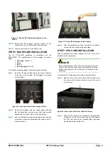
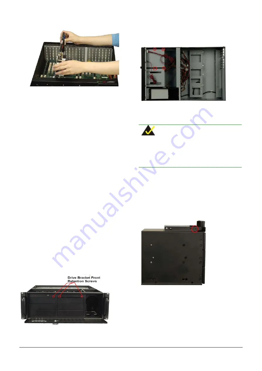
Figure 19:
Slide the CPU Card into the Assigned
Socket
Step 3:
Secure the CPU card to the chassis by reinserting the
retention screw where the slot cover retention screw was
inserted.
Step 0:
STEP 8: PCI/ISA EXPANSION CARD
INSTALLATION
The RACK-3200G chassis can accommodate up to 20
PCI/ISA expansion cards. If you wish to install a PCI
expansion card or an ISA expansion card please follow the
instructions below.
Step 1:
Remove the slot cover at the back of the chassis. To do
this, remove the slot cover retention screw at the top of
the slot cover.
Step 2:
Slide the ISA or PCI expansion card into the backplane
socket reserved for the ISA and PCI expansion cards.
Step 3:
Secure the expansion card to the chassis by reinserting
the retention screw where the slot cover retention screw
was inserted.
Step 0:
STEP 9: DISK DRIVES INSTALLATION
S
TEP
9.1: D
RIVE
B
RACKET
R
EMOVAL
All the drives are installed into two drive brackets at the front of the
chassis. Both drive brackets can hold three 5.25” optical drives.
The drive bracket on the right can also hold a single 3.5” floppy disk
installed on the top. Before the drives can be installed, these drive
brackets must be removed from the chassis.
To remove the drive bracket, follow the steps below.
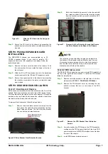
Step 1:
Remove the drive bracket retention screw(s) from the
front panel. The right side drive bracket has two front
panel retention screws. The left side drive bracket
has one front panel retention screw.
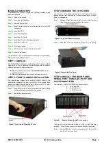
Figure 20: Drive Bracket Front Retention Screws
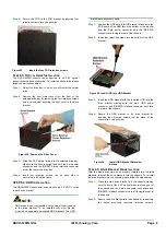
Step 2:
Both drive brackets are secured to the chassis with
two retention screws. Remove the retention screws
from the bracket in which you wish to install the 5.25”
optical drives.
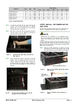
Figure 21:
Remove the Four Retention Screws that Secure
the Drive Bracket to the Base of the Chassis
NOTE:
The retention screws attaching the disk drive brackets to
the bottom of the chassis may be difficult to see. One set
of retention screws is between the two disk drive brackets
and the other set of retention screws is between the drive
bracket and the left side of the chassis.
S
TEP
9.2: FDD I
NSTALLATION
The RACK-3200G chassis can support a single FDD installed at
the top of the right disk drive bracket. To install an FDD please
follow the steps below.
Step 1:
Remove the drive bracket on the right side, to do this,
please refer to
S
TEP
9.1: D
RIVE
B
RACKET
R
EMOVAL
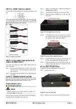
Step 2:
Remove the FDD bracket cover by removing the two
retention screws that are on the sides of the FDD
bracket.
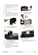
Figure 22:
Remove the FDD Bracket Cover Retention
Screws
Step 3:
Correctly position the FDD drive in the FDD bracket by
making sure the FDD is upright and both the 4-pin FDD
power connector and IDE/SATA interface connector face
the rear of the chassis.
Step 4:
Install FDD bracket retention screws.


