


PPC-F12B/15B/17B/19B-BTi Panel PC
Page 25
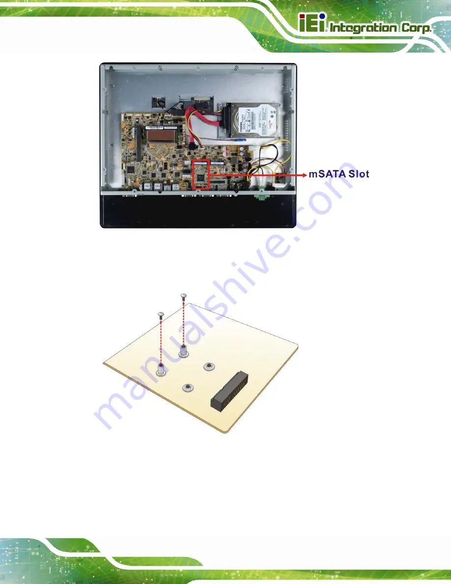
Figure 3-8:
PCIe Mini Card Slot which supports mSATA
Step 3:
Remove the retention screws
. Remove the two retention screws as shown in
.
Figure 3-9: Removing the Retention Screws
Step 4:
Insert into the socket at an angle
. Line up the notch on the card with the notch
on the slot. Slide the PCIe Mini card into the socket at an angle of about 20º
(
Summary of Contents for PPC-F12B
Page 16: ......
Page 17: ...PPC F12B 15B 17B 19B BTi Panel PC Page 1 1 Introduction Chapter 1 ...
Page 29: ...PPC F12B 15B 17B 19B BTi Panel PC Page 13 2 Unpacking Chapter 2 ...
Page 33: ...PPC F12B 15B 17B 19B BTi Panel PC Page 17 3 Installation Chapter 3 ...
Page 75: ...PPC F12B 15B 17B 19B BTi Panel PC Page 59 Chapter 4 4 System Maintenance ...
Page 77: ...PPC F12B 15B 17B 19B BTi Panel PC Page 61 5 BIOS Setup Chapter 5 ...
Page 112: ...PPC F12B 15B 17B 19B BTi Panel PC Page 96 6 Interface Connectors Chapter 6 ...
Page 132: ...PPC F12B 15B 17B 19B BTi Panel PC Page 116 Appendix A A Regulatory Compliance ...
Page 137: ...PPC F12B 15B 17B 19B BTi Panel PC Page 121 B BIOS Configuration Options Appendix B ...
Page 140: ...PPC F12B 15B 17B 19B BTi Panel PC Page 124 C Safety Precautions Appendix C ...
Page 146: ...PPC F12B 15B 17B 19B BTi Panel PC Page 130 D Watchdog Timer Appendix D ...
Page 149: ...PPC F12B 15B 17B 19B BTi Panel PC Page 133 Appendix E E Hazardous Materials Disclosure ...


