


PPC-F06B-BT Panel PC
Page 19
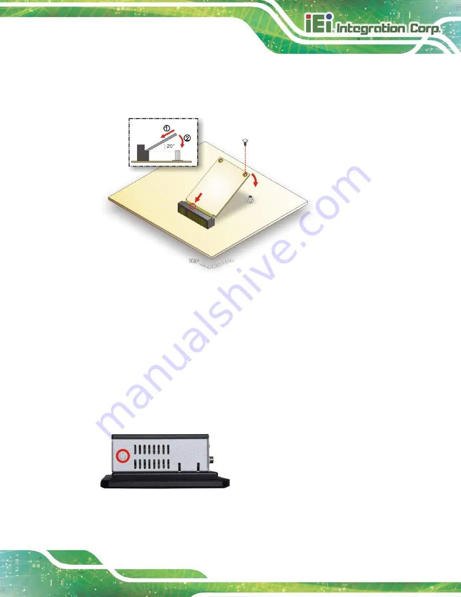
Step 4:
Secure the mSATA module with the retention screw. Push the other end of the
mSATA module down and secure the module with the previously removed
retention screw (
).
Figure 3-5: mSATA Module Installation
Step 5:
Replace the back cover and secure it with retention screws.
3.8 Wireless LAN Module Installation (Optional)
To install the optional wireless LAN (WLAN) module, please follow the steps below.
Step 1:
Remove the back cover. See
Section 3.5
Step 2:
Remove the two knockouts for antenna installation. The two knockouts are
located on the side panels of the PPC-F06B-BT, one on each side.
Figure 3-6: Knockout for Wireless Antenna (Left Side Panel)
Summary of Contents for PPC-F06B-BT
Page 13: ...PPC F06B BT Panel PC Page 1 1 Introduction Chapter 1 ...
Page 18: ...PPC F06B BT Panel PC Page 6 1 7 Dimensions Figure 1 6 PPC F06B BT Dimensions mm ...
Page 21: ...PPC F06B BT Panel PC Page 9 2 Unpacking Chapter 2 ...
Page 25: ...PPC F06B BT Panel PC Page 13 3 Installation Chapter 3 ...
Page 52: ...PPC F06B BT Panel PC Page 40 4 BIOS Setup Chapter 4 ...
Page 80: ...PPC F06B BT Panel PC Page 68 5 Interface Connectors Chapter 5 ...
Page 92: ...PPC F06B BT Panel PC Page 80 Appendix A A Regulatory Compliance ...
Page 98: ...PPC F06B BT Panel PC Page 86 B BIOS Configuration Options Appendix B ...
Page 101: ...PPC F06B BT Panel PC Page 89 C Safety Precautions Appendix C ...
Page 107: ...PPC F06B BT Panel PC Page 95 D Watchdog Timer Appendix D ...
Page 110: ...PPC F06B BT Panel PC Page 98 Appendix E E Hazardous Materials Disclosure ...


