PPC-FxxC-Q370
Page 28
Step 5:
Once aligned, press down until the DIMM is properly seated. Clip the two
handles into place. See
Step 6:
To remove a DIMM, push both handles outward. The memory module is ejected
by a mechanism in the socket.
Step 0:
CAUTION:
For dual channel configuration, install two identical memory modules
that feature the same capacity, timings, voltage, number of ranks and
the same brand.
3.7 M.2 SSD Installation (Optional)
The two M.2 M-key slots allow installation of M.2 2280 cards. To install an M.2 card,
please follow the steps below.
Step 1:
Remove the rear cover. See
Section 3.5
Step 2:
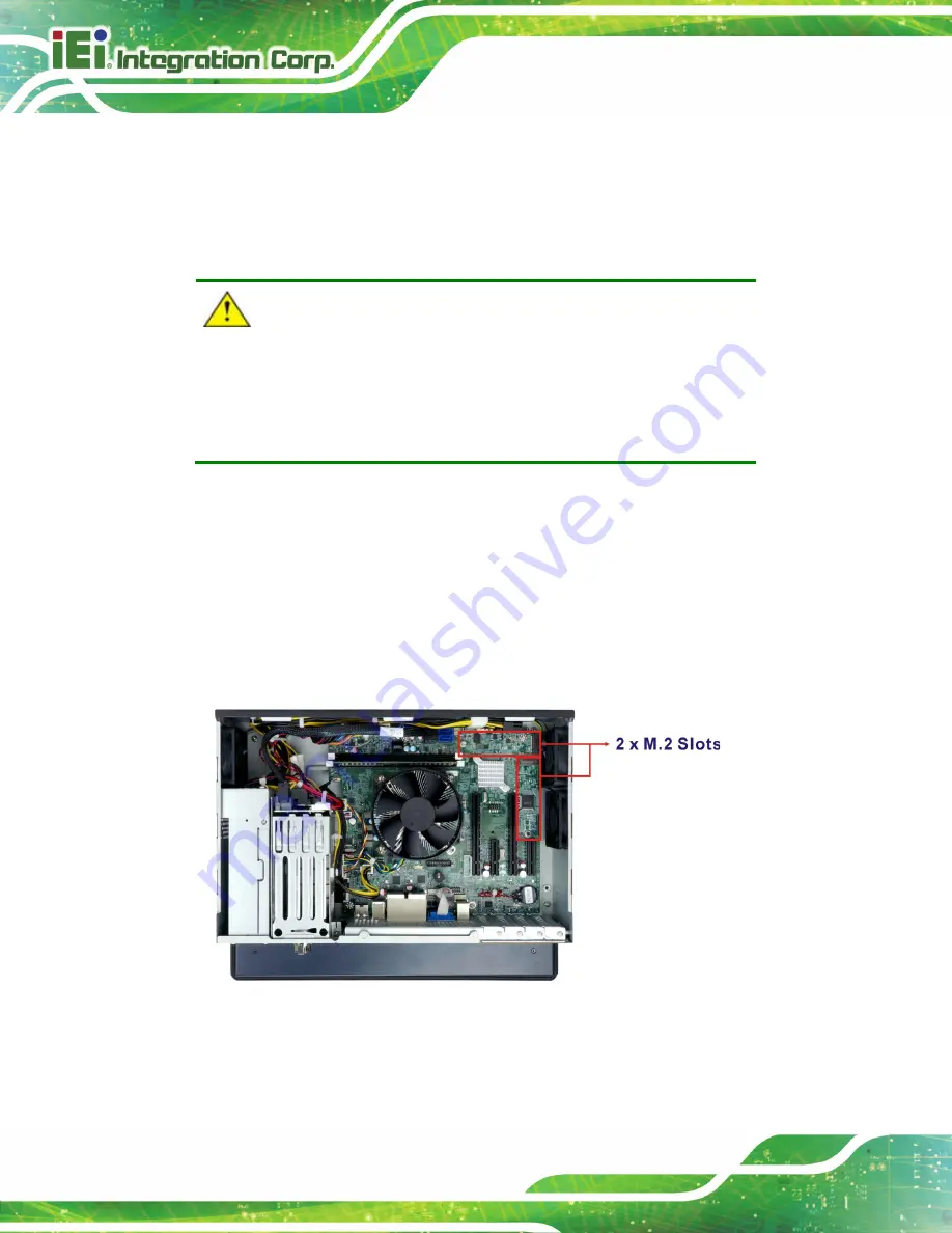
Locate the M.2 slot as shown in
Figure 3-9: M.2 Slot Locations
Step 3:
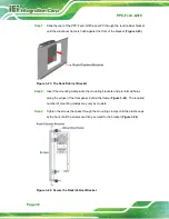
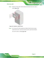
Remove the on-board retention screw as shown in
Summary of Contents for PPC-F C-Q370 Series
Page 17: ...PPC FxxC Q370 Page xvii BIOS Menu 31 Save Exit 87 ...
Page 18: ......
Page 19: ...PPC FxxC Q370 Page 1 Chapter 1 1 Introduction ...
Page 35: ...PPC FxxC Q370 Page 17 Chapter 2 2 Unpacking ...
Page 38: ...PPC FxxC Q370 Page 20 Chapter 3 3 Installation ...
Page 63: ...PPC FxxC Q370 Page 45 Chapter 4 4 BIOS ...
Page 106: ...PPC FxxC Q370 Page 88 Chapter 5 5 Troubleshooting and Maintenance ...
Page 110: ...PPC FxxC Q370 Page 92 6 Interface Connectors Chapter 6 ...
Page 125: ...PPC FxxC Q370 Page 107 Appendix A A Regulatory Compliance ...
Page 130: ...PPC FxxC Q370 Page 112 B Safety Precautions Appendix B ...
Page 136: ...PPC FxxC Q370 Page 118 Appendix C C BIOS Menu Options ...
Page 139: ...PPC FxxC Q370 Page 121 Appendix D D Watchdog Timer ...
Page 142: ...PPC FxxC Q370 Page 124 Appendix E E Error Beep Code ...
Page 144: ...PPC FxxC Q370 Page 126 Appendix F F Hazardous Materials Disclosure ...


