PPC-51xxA-G41/WIDS-51xA-G41 Panel PC
Page 110
Figure 6-1: DIMM Socket Clip Locations
Step 3:
Push the new DIMM module until it engages and the white plastic end clips click
into place. Make sure the end clips are fully secured after installation.
Step 0:
6.5 Elevated Platform Removal
The elevated platform supports the optical drive and the hard drive. It is not necessary to
remove the optical drive bracket or hard drive bracket to remove the elevated platform.
Step 1:
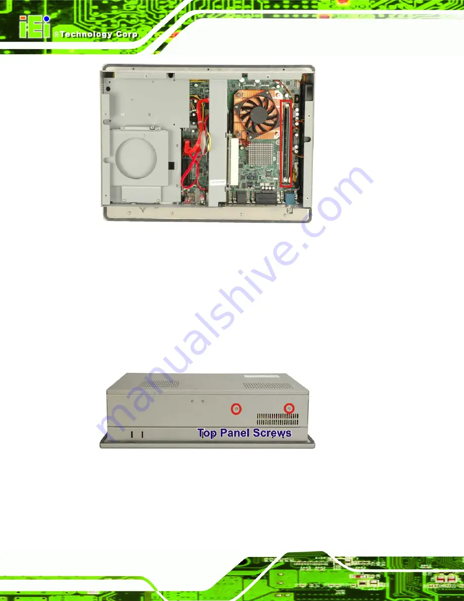
Unfasten the elevated platform screws on the top panel (
Figure 6-2: Top Panel Elevated Platform Screws
Summary of Contents for PPC-5150A-G41
Page 13: ...PPC 51xxA G41 WIDS 51xA G41 Panel PC Page 1 Chapter 1 1 Introduction ...
Page 22: ...PPC 51xxA G41 WIDS 51xA G41 Panel PC Page 10 Chapter 2 2 Specifications ...
Page 40: ...PPC 51xxA G41 WIDS 51xA G41 Panel PC Page 28 Chapter 3 3 Unpacking ...
Page 44: ...PPC 51xxA G41 WIDS 51xA G41 Panel PC Page 32 Chapter 4 4 Installation and Configuration ...
Page 77: ...PPC 51xxA G41 WIDS 51xA G41 Panel PC Page 65 Chapter 5 5 BIOS Setup ...
Page 78: ...PPC 51xxA G41 WIDS 51xA G41 Panel PC Page 66 ...
Page 119: ...PPC 51xxA G41 WIDS 51xA G41 Panel PC Page 107 Chapter 6 6 System Maintenance ...
Page 129: ...PPC 51xxA G41 WIDS 51xA G41 Panel PC Page 117 Appendix A A BIOS Options ...
Page 133: ...PPC 51xxA G41 WIDS 51xA G41 Panel PC Page 121 Appendix B B Terminology ...
Page 137: ...PPC 51xxA G41 WIDS 51xA G41 Panel PC Page 125 Appendix C C Digital I O Interface ...
Page 140: ...PPC 51xxA G41 WIDS 51xA G41 Panel PC Page 128 Appendix D D Watchdog Timer ...
Page 143: ...PPC 51xxA G41 WIDS 51xA G41 Panel PC Page 131 Appendix E E Address Mapping ...
Page 146: ...PPC 51xxA G41 WIDS 51xA G41 Panel PC Page 134 Figure E 3 Input Output IO 2 of 2 ...
Page 148: ...PPC 51xxA G41 WIDS 51xA G41 Panel PC Page 136 E 4 Memory Figure E 5 Memory ...
Page 149: ...PPC 51xxA G41 WIDS 51xA G41 Panel PC Page 137 Appendix F F Hazardous Materials Disclosure ...

