


PPC-37xxA-N26 Panel PC
Page 119
Figure 7-2: Main Board Layout Diagram (Solder Side)
7.2 Internal Peripheral Connectors
Internal peripheral connectors are found on the motherboard and are only accessible
when the motherboard is outside of the chassis. The table below shows a list of the
peripheral interface connectors on the PPC-37xxA-N26 motherboard. Pinouts of these
connectors can be found in the following sections.
Connector
Type
Label
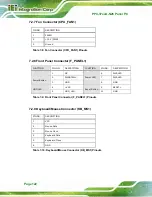
5 V SATA power connectors
2-pin wafer
SATA_PWR1,
SATA_PWR2
Audio connector
10-pin header
AUDIO1
Backlight inverter connector
5-pin wafer
INV1
Battery connector
2-pin wafer
BAT1
Buzzer connector
2-pin wafer
SP1
Digital Input/Output (DIO) connector
10-pin header
DIO1
Summary of Contents for PPC-37 A-N26 Series
Page 17: ...PPC 37xxA N26 Panel PC Page 1 1 Introduction Chapter 1 ...
Page 29: ...PPC 37xxA N26 Panel PC Page 13 2 Unpacking Chapter 2 ...
Page 34: ...PPC 37xxA N26 Panel PC Page 18 3 Installation Chapter 3 ...
Page 72: ...PPC 37xxA N26 Panel PC Page 56 Chapter 4 4 System Maintenance ...
Page 76: ...PPC 37xxA N26 Panel PC Page 60 5 BIOS Setup Chapter 5 ...
Page 106: ...PPC 37xxA N26 Panel PC Page 90 6 Driver Installation Chapter 6 ...
Page 133: ...PPC 37xxA N26 Panel PC Page 117 7 Interface Connectors Chapter 7 ...
Page 145: ...PPC 37xxA N26 Panel PC Page 129 A BIOS Configuration Options Appendix A ...
Page 148: ...PPC 37xxA N26 Panel PC Page 132 Appendix B B One Key Recovery ...
Page 156: ...PPC 37xxA N26 Panel PC Page 140 Figure B 5 Partition Creation Commands ...
Page 189: ...PPC 37xxA N26 Panel PC Page 173 C Safety Precautions Appendix C ...
Page 194: ...PPC 37xxA N26 Panel PC Page 178 D Watchdog Timer Appendix D ...
Page 197: ...PPC 37xxA N26 Panel PC Page 181 E Hazardous Materials Disclosure Appendix E ...


