IEI Technology NANO-CV-D25502/N26002 User Manual Download Page 44


NANO-CV-D25502/N26002 EPIC SBC 

Page 29

Pin 

Description 

Pin 

Description 

USB_VCC 

GND 

DATA- 

DATA+ 

DATA+ 

DATA- 

GND 

USB_VCC 

Table 3-17: USB Connector Pinouts 

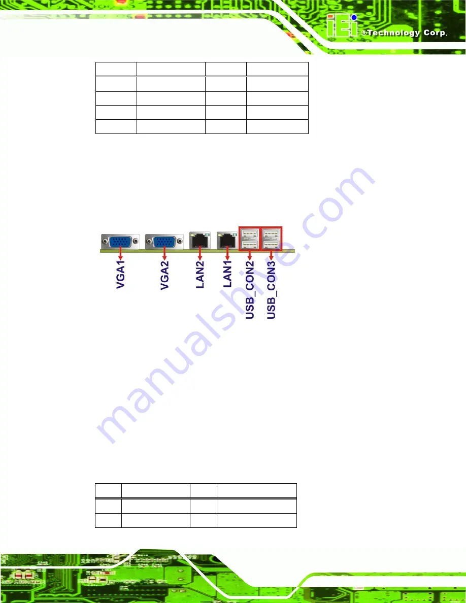
3.3 External Peripheral Interface Connector Panel 

The figure below shows the external periphe4ral interface connector (EPIC) panel. The 

EPIC panel consists of the following: 


Figure 3-18: External Peripheral Interface Connector


3.3.1 Ethernet Connectors 

CN Label: 

LAN1, LAN2 

CN Type: 

RJ-45 connector 

CN Location: 

See 

Figure 3-18


CN Pinouts: 

See 

Table 3-18


The NANO-CV-D25502/N26002 is equipped with two built-in RJ-45 Ethernet controllers. 

Each controller can connect to the LAN through one RJ-45 LAN connector. 

Pin 

Description 

Pin 

Description 

MDI0+ 

MDI2+ 

MDI0- 

MDI2- 

Summary of Contents for NANO-CV-D25502/N26002

Page 1: ...C SBC Page i IEI Technology Corp User Manual EPIC SBC with Intel Atom D2550 N2600 Processor DDR3 Dual VGA LVDS Dual PCIe GbE USB 2 0 Dual PCIe Mini SATA 3Gb s Audio and RoHS MODEL NANO CV D25502 N2600...

Page 2: ...NANO CV D25502 N26002 EPIC SBC Page ii Revision Date Version Changes 27 August 2012 1 00 Initial release...

Page 3: ...mages arising out of the use or inability to use the product or documentation even if advised of the possibility of such damages This document contains proprietary information protected by copyright A...

Page 4: ...CONNECTORS 12 3 1 PERIPHERAL INTERFACE CONNECTORS 13 3 1 1 NANO CV D25502 N26002 Layout 13 3 1 2 Peripheral Interface Connectors 13 3 1 3 External Interface Panel Connectors 14 3 2 INTERNAL PERIPHERA...

Page 5: ...M INSTALLATION 35 4 4 JUMPER SETTINGS 36 4 4 1 AT ATX Power Selection Jumper 36 4 4 2 Clear CMOS Jumper 37 4 4 3 LVDS1 Voltage Selection 38 4 4 4 mSATA PCIe Mini Selection 39 4 5 CHASSIS INSTALLATION...

Page 6: ...6 Super IO Configuration 64 5 3 6 1 Serial Port n Configuration 65 5 3 7 F81866 H W Monitor 69 5 3 7 1 Smart Fan Mode Configuration 70 5 3 8 Serial Port Console Redirection 71 5 3 9 iEi Feature 73 5 4...

Page 7: ...5 RECOVERY TOOL FUNCTIONS 128 B 5 1 Factory Restore 130 B 5 2 Backup System 131 B 5 3 Restore Your Last Backup 132 B 5 4 Manual 133 B 6 RESTORE SYSTEMS FROM A LINUX SERVER THROUGH LAN 134 B 6 1 Confi...

Page 8: ...le the DIO Input Function 151 D 3 2 Enable the DIO Output Function 151 E WATCHDOG TIMER 152 F HAZARDOUS MATERIALS DISCLOSURE 155 F 1 HAZARDOUS MATERIALS DISCLOSURE TABLE FOR IPB PRODUCTS CERTIFIED AS...

Page 9: ...Location 20 Figure 3 9 Keyboard Mouse Connector Location 21 Figure 3 10 LVDS1 Connector Location 22 Figure 3 11 PCIe Mini Card Slot Locations 23 Figure 3 12 Power Connector Location 24 Figure 3 13 RS...

Page 10: ...ure 6 5 Chipset Driver License Agreement 87 Figure 6 6 Chipset Driver Read Me File 87 Figure 6 7 Chipset Driver Setup Operations 88 Figure 6 8 Chipset Driver Installation Finish Screen 89 Figure 6 9 V...

Page 11: ...eation Confirmation 119 Figure B 19 Image Creation Complete 119 Figure B 20 Image Creation Complete 119 Figure B 21 Press Any Key to Continue 120 Figure B 22 Auto Recovery Utility 121 Figure B 23 Disa...

Page 12: ...SBC Page xii Figure B 39 System Backup Complete Window 131 Figure B 40 Restore Backup 132 Figure B 41 Restore System Backup Complete Window 132 Figure B 42 Symantec Ghost Window 133 Figure B 43 Disabl...

Page 13: ...ble 3 9 Front Panel Connector Pinouts 20 Table 3 10 Keyboard Mouse Connector Pinouts 21 Table 3 11 LVDS1 Connector Pinouts 22 Table 3 12 PCIe Mini Card Slot Pinouts 24 Table 3 13 Power Connector Pinou...

Page 14: ...NANO CV D25502 N26002 EPIC SBC Page xiv Table 5 1 BIOS Navigation Keys 56...

Page 15: ...er IO Configuration 64 BIOS Menu 9 Serial Port n Configuration Menu 65 BIOS Menu 10 F81866 H W Monitor 69 BIOS Menu 11 Smart Fan Mode Configuration 70 BIOS Menu 12 Serial Port Console Redirection 71 B...

Page 16: ...NANO CV D25502 N26002 EPIC SBC Page 1 Chapter 1 1 Introduction...

Page 17: ...bit LVDS screens Maximum six USB ports two SATA 3Gb s connectors two PCIe Mini card slots four COM ports and one audio connector provide flexible expansion options 1 2 Model Variations The model vari...

Page 18: ...800 MHz DDR3 SO DIMM supports up to 4 GB Easy assembly thermal design by heat sink enclosure Wide range power input 9V 28V Full size PCIe Mini card slot with mSATA support Dual GbE RoHS compliant 1 4...

Page 19: ...N26002 EPIC SBC Page 4 1 5 Dimensions The main dimensions of the NANO CV D25502 N26002 are shown in the diagram below Figure 1 3 NANO CV D25502 N26002 Dimensions mm Figure 1 4 External Interface Panel...

Page 20: ...NANO CV D25502 N26002 EPIC SBC Page 5 1 6 Data Flow 6Figure 1 5 shows the data flow between the system chipset the CPU and other components installed on the motherboard Figure 1 5 Data Flow Diagram...

Page 21: ...e speed N2600 Intel GMA 3600 with 400 MHz graphics core speed Display Dual display supported First VGA is integrated in the CPU 1920 x 1200 Second VGA is driven by the NXP PTN3392 1920 x 1200 One LVDS...

Page 22: ...Six USB 2 0 1 1 devices supported Four by external connectors Two by on board pin header Power Supply 9V 28V AT and ATX support One internal 4 pin 2x2 power connector Power Consumption 12V 1 59 A 1 8...

Page 23: ...NANO CV D25502 N26002 EPIC SBC Page 8 Chapter 2 2 Packing List...

Page 24: ...ischarge Self grounding Touch a grounded conductor every few minutes to discharge any excess static buildup Use an anti static pad When configuring any circuit board place it on an anti static mat Onl...

Page 25: ...02 was purchased from or contact an IEI sales representative directly by sending an email to 32sales iei com tw The NANO CV D25502 N26002 is shipped with the following components Quantity Item and Par...

Page 26: ...Installation Guide Table 2 1 Packing List 2 4 Optional Items The following are optional components which may be separately purchased Item and Part Number Image Dual USB cable wo bracket P N 32000 0703...

Page 27: ...NANO CV D25502 N26002 EPIC SBC Page 12 Chapter 3 3 Connectors...

Page 28: ...1 NANO CV D25502 N26002 Layout The figure below shows all the connectors and jumpers Figure 3 1 Connectors and Jumpers 3 1 2 Peripheral Interface Connectors The table below lists all the connectors on...

Page 29: ...M_PCIE2 Power connector 9V 28V 4 pin connector CN2 RS 232 serial port connectors 10 pin header COM1 COM2 COM3 RS 422 485 serial port connector 4 pin wafer COM4 Serial ATA SATA drive connectors 7 pin...

Page 30: ...SATA_PWR2 CN Type 2 pin wafer CN Location See Figure 3 2 CN Pinouts See Table 3 3 Use the 5 V SATA power connectors to connect to SATA device power connection Figure 3 2 5 V SATA Power Connector Loca...

Page 31: ...tor Location Pin Description Pin Description 1 SPK_R 2 LINE1_R 3 AUD_GND 4 AUD_GND 5 SPK _L 6 LINE1_L 7 AUD_GND 8 AUD_GND 9 MIC1_R 10 MIC1_L Table 3 4 Audio Connector Pinouts 3 2 3 Backlight Inverter...

Page 32: ...Table 3 5 Backlight Inverter Connector Pinouts 3 2 4 Battery Connector CAUTION Risk of explosion if battery is replaced by an incorrect type Only certified engineers should replace the on board batter...

Page 33: ...Battery Connector Location Pin Description 1 Battery 2 GND Table 3 6 Battery Connector Pinouts 3 2 5 Digital Input Output DIO Connector CN Label DIO1 CN Type 10 pin header CN Location See Figure 3 6 C...

Page 34: ...Input 1 10 Input 0 Table 3 7 Digital I O Connector Pinouts 3 2 6 Fan Connectors CN Label CPU_FAN1 SYS_FAN1 CN Type 3 pin wafer CN Location See Figure 3 7 CN Pinouts See Table 3 8 The fan connectors at...

Page 35: ...and buttons on the computer s front panel Figure 3 8 Front Panel Connector Location Function Pin Description Function Pin Description 1 NC 6 PWRLED 2 PWRBTSW 7 PWRLED Power Button 3 GND Power LED 8 G...

Page 36: ...Figure 3 9 Keyboard Mouse Connector Location Pin Description 1 VCC 2 Mouse Data 3 Mouse Clock 4 Keyboard Data 5 Keyboard Clock 6 GND Table 3 10 Keyboard Mouse Connector Pinouts 3 2 9 LVDS1 Connector...

Page 37: ...VDS_CLK 11 NC 12 NC 13 GND 14 GND 15 LDDC_DATA 16 LDDC_CLK 17 VCC_LCD 18 VCC_LCD 19 VCC_LCD 20 VCC_LCD Table 3 11 LVDS1 Connector Pinouts 3 2 10 PCIe Mini Card Slots CN Label M_PCIE1 M_PCIE2 CN Type 5...

Page 38: ...SATA device is installed to the M_PCIE1 slot Figure 3 11 PCIe Mini Card Slot Locations Pin Description Pin Description 1 PCIE_WAKE 2 VCC3 3 N C 4 GND 5 N C 6 1 5V 7 N C 8 N C 9 GND 10 N C 11 PCIE_CLK...

Page 39: ...7 N C 48 1 5V 49 N C 50 GND 51 M SATA Detect 52 VCC3 Table 3 12 PCIe Mini Card Slot Pinouts 3 2 11 Power Connector 9V 28V CN Label CN2 CN Type 4 pin connector CN Location See Figure 3 12 CN Pinouts Se...

Page 40: ...Connectors CN Label COM1 COM2 COM3 CN Type 10 pin header CN Location See Figure 3 13 CN Pinouts See Table 3 14 Each of these connectors provides RS 232 connections Figure 3 13 RS 232 Serial Port Conn...

Page 41: ...3 15 NOTE These pins are shared with those on the main serial port Use either the pins on the main connector or on this connector but not both This connector provides RS 422 or RS 485 communications F...

Page 42: ...inouts See Table 3 16 The SATA drive connectors can be connected to SATA drives and support up to 3Gb s data transfer rate NOTE The SATA1 connector will be disabled when an mSATA device is installed t...

Page 43: ...n See Figure 3 16 The SO DIMM connector is for installing memory on the system Figure 3 16 SO DIMM Connector Location 3 2 16 USB Connector CN Label USB4 CN Type 8 pin header CN Location See Figure 3 1...

Page 44: ...interface connector EPIC panel The EPIC panel consists of the following Figure 3 18 External Peripheral Interface Connector 3 3 1 Ethernet Connectors CN Label LAN1 LAN2 CN Type RJ 45 connector CN Loc...

Page 45: ...linked blinking data is being sent received B off 10 Mb s green 100 Mb s orange 1000 Mb s Table 3 19 RJ 45 Ethernet Connector LEDs 3 3 2 USB Connectors CN Label USB_CON2 USB_CON3 CN Type Dual USB por...

Page 46: ...e 3 18 CN Pinouts See Figure 3 20 and Table 3 21 Each VGA connector connects to a monitor that accepts a standard VGA input Pin Description Pin Description 1 RED 2 GREEN 3 BLUE 4 NC 5 GND 6 GND 7 GND...

Page 47: ...NANO CV D25502 N26002 EPIC SBC Page 32 Chapter 4 4 Installation...

Page 48: ...i static wristband can help to prevent ESD from damaging the board Self grounding Before handling the board touch any grounded conducting material During the time the board is handled frequently touch...

Page 49: ...helps prevent ESD damage Place the NANO CV D25502 N26002 on an antistatic pad o When installing or configuring the motherboard place it on an antistatic pad This helps to prevent potential ESD damage...

Page 50: ...e follow the steps below and refer to Figure 4 1 Figure 4 1 SO DIMM Installation Step 1 Locate the SO DIMM socket Place the NANO CV D25502 N26002 on an anti static pad with the solder side facing up S...

Page 51: ...connecting the pins of the jumper with the plastic clip and to OPEN a jumper means removing the plastic clip from a jumper The hardware jumpers must be set before installation Jumpers are shown in Ta...

Page 52: ...Selection Jumper Location 4 4 2 Clear CMOS Jumper Jumper Label JP2 Jumper Type 3 pin header Jumper Settings See Table 4 3 Jumper Location See Figure 4 3 To reset the BIOS move the jumper to the Clear...

Page 53: ...voltage is selected with this jumper Please refer to the user guide that came with the monitor to select the correct voltage Jumper Label JP3 Jumper Type 3 pin header Jumper Settings See Table 4 4 Ju...

Page 54: ...2 pin header Jumper Settings See Table 4 5 Jumper Location See Figure 4 5 The mSATA PCIe Mini mode selection jumper specifies the M_PCIE1 connector as MSATA or PCIe Mini mode Setting Description Off A...

Page 55: ...ndividual power supply unit the cooling fan of a power supply can also help generate airflow through the board surface NOTE IEI has a wide range of chassis available Please contact your NANO CV D25502...

Page 56: ...ly power cord from its AC power source to prevent a sudden power surge to the NANO CV D25502 N26002 Step 1 Locate the power cable The power cable is shown in the packing list in Chapter 2 Step 2 Conne...

Page 57: ...audio connector on the NANO CV D25502 N26002 The audio kit consists of three audio jacks One audio jack Mic In connects to a microphone The remaining two audio jacks Line In and Line Out connect to tw...

Page 58: ...NO CV D25502 N26002 can be connected to a TFT LCD screen through the LVDS crimp connectors on the board To connect a TFT LCD to the NANO CV D25502 N26002 please follow the steps below Step 1 Locate th...

Page 59: ...refer to the installation manual that came with the TFT LCD screen Figure 4 9 LVDS Connector Step 3 Locate the backlight inverter connector The location of the backlight inverter connector is shown in...

Page 60: ...NANO CV D25502 N26002 EPIC SBC Page 45 Figure 4 10 Backlight Inverter Connection...

Page 61: ...low Figure 4 11 PCIe Mini Card Installation Step 1 Insert into the socket at and angle Line up the notch on the card with the notch on the connector Slide the PCIe Mini card into the socket at an angl...

Page 62: ...nnectors are shown in Chapter 3 Step 2 Insert the cable connector Insert the cable connector into the on board SATA drive connector and the SATA power connector See Figure 4 12 Figure 4 12 SATA Drive...

Page 63: ...shown in Chapter 3 Step 2 Insert the cable connector Insert the connector into the serial port header See Figure 4 13 A key on the front of the cable connector ensures the connector can only be instal...

Page 64: ...ct a LAN cable with an RJ 45 connector please follow the instructions below Step 1 Locate the RJ 45 connector The locations of the RJ 45 connectors are shown in Chapter 3 Step 2 Align the connectors A...

Page 65: ...the steps below to connect USB devices to the NANO CV D25502 N26002 Step 1 Locate the USB Series A receptacle connectors The locations of the USB Series A receptacle connectors are shown in Chapter 3...

Page 66: ...connectors are shown in Chapter 3 Step 2 Align the VGA connector Align the male DB 15 connector on the VGA screen cable with the female DB 15 connector on the external peripheral interface Step 3 Inse...

Page 67: ...6002 do not put the NANO CV D25502 N26002 directly on a surface that can not dissipate system heat especially the wooden or plastic desk It is highly recommended to run the NANO CV D25502 N26002 on a...

Page 68: ...NANO CV D25502 N26002 EPIC SBC Page 53 Figure 4 17 Heat Sink Retention Screws...

Page 69: ...NANO CV D25502 N26002 EPIC SBC Page 54 Chapter 5 5 BIOS...

Page 70: ...nter SETUP message appears on the screen If the message disappears before the DEL or F2 key is pressed restart the computer and try again 5 1 2 Using Setup Use the arrow keys to highlight items press...

Page 71: ...ars To exit the Help Window press ESC or the F1 key again 5 1 4 Unable to Reboot after Configuration Changes If the computer cannot boot after changes to the system configuration is made CMOS defaults...

Page 72: ...Use Tab to switch between Data elements Select Screen Select Item Enter Select Change Opt F1 General Help F2 Previous Values F3 Optimized Defaults F4 Save Exit ESC Exit Version 2 14 1219 Copyright C...

Page 73: ...o Setup Utility Copyright C 2011 American Megatrends Inc Main Advanced Chipset Boot Security Save Exit ACPI Settings RTC Wake Settings CPU Configuration IDE Configuration USB Configuration F81866 Supe...

Page 74: ...Megatrends Inc BIOS Menu 3 ACPI Settings ACPI Sleep State S1 CPU Stop Clock Use the ACPI Sleep State option to specify the sleep state the system enters when it is not being used S1 CPU Stop Clock DEF...

Page 75: ...erican Megatrends Inc BIOS Menu 4 RTC Wake Settings Wake system with Fixed Time Disabled Use the Wake system with Fixed Time option to enable or disable the system wake on alarm event Disabled DEFAULT...

Page 76: ...Hyper Threading Technology Select Screen Select Item Enter Select Change Opt F1 General Help F2 Previous Values F3 Optimized Defaults F4 Save Exit ESC Exit Version 2 14 1219 Copyright C 2011 American...

Page 77: ...ystem Aptio Setup Utility Copyright C 2011 American Megatrends Inc Advanced SATA Port0 Not Present SATA Port1 Not Present Configure SATA as IDE Select a configuration for SATA Controller Select Screen...

Page 78: ...General Help F2 Previous Values F3 Optimized Defaults F4 Save Exit ESC Exit Version 2 14 1219 Copyright C 2011 American Megatrends Inc BIOS Menu 7 USB Configuration USB Devices The USB Devices field l...

Page 79: ...tio Setup Utility Copyright C 2011 American Megatrends Inc Advanced F81866 Super IO Configuration F81866 Super IO Chip F81866 Serial Port 1 Configuration Serial Port 2 Configuration Serial Port 3 Conf...

Page 80: ...Exit Version 2 14 1219 Copyright C 2011 American Megatrends Inc BIOS Menu 9 Serial Port n Configuration Menu 5 3 6 1 1 Serial Port 1 Configuration Serial Port Enabled Use the Serial Port option to ena...

Page 81: ...T Enable the serial port Change Settings Auto Use the Change Settings option to change the serial port IO port address and interrupt address Auto DEFAULT The serial port IO port address and interrupt...

Page 82: ...O 3E8h IRQ 10 Serial Port I O port address is 3E8h and the interrupt address is IRQ10 IO 3F8h IRQ 10 11 Serial Port I O port address is 3F8h and the interrupt address is IRQ10 11 IO 2F8h IRQ 10 11 Ser...

Page 83: ...O 2E8h IRQ 10 Serial Port I O port address is 2E8h and the interrupt address is IRQ10 IO 3F8h IRQ 10 11 Serial Port I O port address is 3F8h and the interrupt address is IRQ10 11 IO 2F8h IRQ 10 11 Ser...

Page 84: ...GFX 1 680 V V1 05S 1 056 V V1 5_DDR3 1 520 V VSB5V 4 968 V V3 3S 3 360 V VSB3V 3 392 V VBAT 3 264 V Smart Fan Mode Select Select Screen Select Item Enter Select Change Opt F1 General Help F2 Previous...

Page 85: ...rature 3 40 System Temperature 4 30 Smart Fan Mode Select Select Screen Select Item Enter Select Change Opt F1 General Help F2 Previous Values F3 Optimized Defaults F4 Save Exit ESC Exit Version 2 14...

Page 86: ...rection Settings Console Redirection Enable or Disable Select Screen Select Item Enter Select Change Opt F1 General Help F2 Previous Values F3 Optimized Defaults F4 Save Exit ESC Exit Version 2 14 121...

Page 87: ...e serial port transmission speed at 115200 Data Bits 8 Use the Data Bits option to specify the number of data bits 7 Sets the data bits at 7 8 DEFAULT Sets the data bits at 8 Parity None Use the Parit...

Page 88: ...nced iEi Feature Auto Recovery Function Disabled Auto Recovery Function Reboot and recover system automatically within 10 min when OS crashes Please install Auto Recovery API service before enabling t...

Page 89: ...ight C 2011 American Megatrends Inc Main Advanced Chipset Boot Security Save Exit Host Bridge South Bridge Host Bridge Parameters Select Screen Select Item Enter Select Change Opt F1 General Help F2 P...

Page 90: ...Intel IGD Configuration Use the Intel IGD Configuration submenu BIOS Menu 16 to configure the video device connected to the system Aptio Setup Utility Copyright C 2011 American Megatrends Inc Advance...

Page 91: ...system Configuration options are listed below 640x480 LVDS 800x600 LVDS DEFAULT 1024x768 LVDS 1280x1024 LVDS 1366x768 LVDS 1224x600 LVDS 1280x800 LVDS Backlight Control Inverted Use the Backlight Cont...

Page 92: ...ues F3 Optimized Defaults F4 Save Exit ESC Exit Version 2 14 1219 Copyright C 2011 American Megatrends Inc BIOS Menu 17 South Bridge Configuration Restore AC Power Loss Last State Use the Restore AC P...

Page 93: ...on ROM Messages Force BIOS UEFI Boot Disabled Boot Option Priorities Select the keyboard NumLock state Select Screen Select Item Enter Select Change Opt F1 General Help F2 Previous Values F3 Optimized...

Page 94: ...d DEFAULT OEM Logo displayed instead of POST messages Launch PXE OpROM Disabled Use the Launch PXE OpROM option to enable or disable boot option for legacy network devices Disabled DEFAULT Ignore all...

Page 95: ...will have Administrator rights The password length must be in the following range Minimum length 3 Maximum length 20 Administrator Password User Password Set Setup Administrator Password Select Scree...

Page 96: ...Menu 20 Save Exit Save Changes and Reset Use the Save Changes and Reset option to save the changes made to the BIOS options and reset the system Discard Changes and Reset Use the Discard Changes and R...

Page 97: ...NANO CV D25502 N26002 EPIC SBC Page 82 6 Software Drivers Chapter 6...

Page 98: ...pdates The following drivers can be installed on the system Chipset VGA LAN Audio Installation instructions are given below 6 2 Starting the Driver Program To access the driver installation programs p...

Page 99: ...NANO CV D25502 N26002 EPIC SBC Page 84 Figure 6 1 Start Up Screen Step 3 Click NANO CV D25502 N26002 Step 4 The list of drivers in Figure 6 2 appears Figure 6 2 Drivers...

Page 100: ...1 Chipset Step 3 Go to the 32 bit or 64 bit folder that corresponds to your OS version Step 4 Open the Intel Chipset Software Installation Utility folder Step 5 Double click the infinst_autol icon Ste...

Page 101: ...2 N26002 EPIC SBC Page 86 Figure 6 4 Chipset Driver Welcome Screen Step 8 Click Next to continue Step 9 The license agreement in Figure 6 5 appears Step 10 Read the License Agreement Step 11 Click Yes...

Page 102: ...Page 87 Figure 6 5 Chipset Driver License Agreement Step 12 The Read Me file in Figure 6 6 appears Step 13 Click Next to continue Figure 6 6 Chipset Driver Read Me File Step 14 Setup Operations are pe...

Page 103: ...igure 6 7 Chipset Driver Setup Operations Step 15 Once the Setup Operations are complete click Next to continue Step 16 The Finish screen appears Step 17 Select Yes I want to restart the computer now...

Page 104: ...ation To install the VGA driver please do the following Step 1 Access the driver list See Section 6 2 Step 2 Click 2 Graphics Step 3 Open the 32 bit or 64 bit folder that corresponds to your OS versio...

Page 105: ...502 N26002 EPIC SBC Page 90 Figure 6 9 VGA Driver Welcome Screen Step 7 Click Next to continue Step 8 The license agreement in Figure 6 10 appears Step 9 Read the License Agreement Step 10 Click Yes t...

Page 106: ...NANO CV D25502 N26002 EPIC SBC Page 91 Figure 6 10 VGA Driver License Agreement Step 11 The Read Me file in Figure 6 11 appears Step 12 Click Next to continue Figure 6 11 VGA Driver Read Me File...

Page 107: ...ed as shown in Figure 6 12 Figure 6 12 VGA Driver Setup Operations Step 14 Once the Setup Operations are complete click the Next icon to continue Step 15 The Finish screen appears Step 16 Select Yes I...

Page 108: ...Driver Installation To install the LAN driver please do the following Step 1 Access the driver list shown in Figure 6 2 See Section 6 2 Step 2 Click 3 LAN Step 3 Go to the Realtek Install_Win7_7048_09...

Page 109: ...IC SBC Page 94 Figure 6 14 LAN Driver Welcome Screen Step 6 Click Next to continue Step 7 Click Next to continue Step 8 The Ready to Install screen in Figure 6 15 appears Step 9 Click Install to proce...

Page 110: ...02 N26002 EPIC SBC Page 95 Figure 6 15 LAN Driver Installation Step 10 The program begins to install Step 11 When the driver installation is complete the screen in Figure 6 16 appears Step 12 Click Fi...

Page 111: ...Audio Driver Installation To install the Audio driver please do the following Step 1 Access the driver list See Section 6 2 Step 2 Click 4 Audio Step 3 Open the Win7 folder Step 4 Double click the Vi...

Page 112: ...IC SBC Page 97 Figure 6 17 Audio Driver Installation File Extraction Step 6 The Welcome screen in Figure 6 18 appears Figure 6 18 Audio Driver Welcome Screen Step 7 Click Next to continue Step 8 The p...

Page 113: ...installation progress can be monitored in the progress bar shown in Figure 6 19 Figure 6 19 Audio Driver Installation Step 10 When the driver installation is complete the screen in Figure 6 20 appear...

Page 114: ...NANO CV D25502 N26002 EPIC SBC Page 99 Step 11 Select Yes I want to restart my computer now and click Finish Step 12 The system reboots...

Page 115: ...NANO CV D25502 N26002 EPIC SBC Page 100 Appendix A A BIOS Options...

Page 116: ...rt Enabled 66 Change Settings Auto 66 Serial Port Enabled 67 Change Settings Auto 67 Serial Port Enabled 68 Change Settings Auto 68 PC Health Status 69 CPU_FAN1 SYS_FAN1 Smart Fan Control Auto Duty Cy...

Page 117: ...Lock State On 78 Quiet Boot Enabled 79 Launch PXE OpROM Disabled 79 Option ROM Messages Force BIOS 79 UEFI Boot Disabled 79 Administrator Password 80 User Password 80 Save Changes and Reset 81 Discard...

Page 118: ...NANO CV D25502 N26002 EPIC SBC Page 103 Appendix B B One Key Recovery...

Page 119: ...from the factory default image after encountering a Blue Screen of Death BSoD or a hang for around 10 minutes Please refer to Section B 3 for the detailed setup procedure The IEI One Key Recovery too...

Page 120: ...be used with IEI products The software will fail to run and a warning message will appear when used on non IEI hardware To create the system backup the main storage device must be split into two part...

Page 121: ...eady installed B 1 2 Supported Operating System The recovery CD is compatible with both Microsoft Windows and Linux operating system OS The supported OS versions are listed below Microsoft Windows o W...

Page 122: ...OTE Installing unsupported OS versions may cause the recovery tool to fail B 2 Setup Procedure for Windows Prior to using the recovery tool to backup or restore a few setup procedures are required Ste...

Page 123: ...he recovery CD Step 4 Turn on the system Step 5 Press the DELETE key as soon as the system is turned on to enter the BIOS Step 6 Select the connected optical disk drive as the 1st boot device Boot Boo...

Page 124: ...When prompted press any key to boot from the recovery CD It will take a while to launch the recovery tool Please be patient Figure B 2 Launching the Recovery Tool Step 3 The recovery tool setup menu...

Page 125: ...the other is for saving recovery files and images which will be an invisible partition Press Enter after entering each line below system32 diskpart DISKPART list vol DISKPART sel disk 0 DISKPART crea...

Page 126: ...NANO CV D25502 N26002 EPIC SBC Page 111 Figure B 5 Partition Creation Commands...

Page 127: ...g system onto the unlabelled partition The partition labeled Recovery is for use by the system recovery tool and should not be used for installing the operating system or any applications NOTE The ope...

Page 128: ...he system Step 3 Boot the system from the recovery CD When prompted press any key to boot from the recovery CD It will take a while to launch the recovery tool Please be patient Figure B 6 Launching t...

Page 129: ...process the partition created for recovery files in Section 78B 2 2 is hidden and the recovery tool is saved in this partition Figure B 8 Building the Recovery Partition Step 6 After completing the sy...

Page 130: ...low the steps below Step 1 Turn on the system When the following screen displays 78Figure B 10 press the F3 key to access the recovery tool The message will display for 10 seconds please press F3 befo...

Page 131: ...ge 116 Figure B 12 About Symantec Ghost Window Step 4 Use mouse to navigate to the option shown below 78Figure B 13 Figure B 13 Symantec Ghost Path Step 5 Select the local source drive Drive 1 as show...

Page 132: ...n in 78Figure B 15 Then click OK Figure B 15 Select a Source Partition from Basic Drive Step 7 Select 1 2 Recovery NTFS drive and enter a file name called iei 78Figure B 16 Click Save The factory defa...

Page 133: ...CV D25502 N26002 EPIC SBC Page 118 Figure B 16 File Name to Copy Image to Step 8 When the Compress Image screen in 78Figure B 17 prompts click High to make the image file smaller Figure B 17 Compress...

Page 134: ...18 Image Creation Confirmation Step 10 The Symantec Ghost starts to create the factory default image 78Figure B 19 Figure B 19 Image Creation Complete Step 11 When the image creation completes a scre...

Page 135: ...h BSoD or a hang for around 10 minutes To use the auto recovery function follow the steps described in the following sections CAUTION The auto recovery function can only run on a Microsoft Windows sys...

Page 136: ...overy CD This utility MUST be installed in the system otherwise the system will automatically restore from the factory default image every ten 10 minutes Figure B 22 Auto Recovery Utility Step 3 Disab...

Page 137: ...t Figure B 24 Launching the Recovery Tool Step 5 When the recovery tool setup menu appears press 4 then Enter Figure B 25 Auto Recovery Environment for Windows Step 6 The Symantec Ghost window appears...

Page 138: ...iguration the following message prompts to confirm whether to create a factory default image Type Y to have the system create a factory default image automatically Type N within 6 seconds to skip this...

Page 139: ...completing the system configuration press any key in the following window to restart the system Figure B 29 Press any key to continue Step 10 Eject the One Key Recovery CD and restart the system Step...

Page 140: ...utomatically restore from the factory default image B 4 Setup Procedure for Linux The initial setup procedures for a Linux system are mostly the same with the procedure for Microsoft Windows Please fo...

Page 141: ...marked in red to create a partition for recovery images system32 diskpart DISKPART list vol DISKPART sel disk 0 DISKPART create part pri size ___ DISKPART assign letter N DISKPART exit system32 forma...

Page 142: ...Figure B 32 System Configuration for Linux Step 5 Access the recovery tool main menu by modifying the menu lst To first access the recovery tool main menu the menu lst must be modified In Linux enter...

Page 143: ...default image B 5 Recovery Tool Functions After completing the initial setup procedures as described above users can access the recovery tool by pressing F3 while booting up the system However if the...

Page 144: ...be saved in the hidden partition 3 Restore your last backup Restore the last system backup image 4 Manual Enter the Symantec Ghost window to configure manually 5 Quit Exit the recovery tool and restar...

Page 145: ...in the main menu Step 2 The Symantec Ghost window appears and starts to restore the factory default A factory default image called iei GHO is created in the hidden Recovery partition Figure B 36 Rest...

Page 146: ...main menu Step 2 The Symantec Ghost window appears and starts to backup the system A backup image called iei_user GHO is created in the hidden Recovery partition Figure B 38 Backup System Step 3 The s...

Page 147: ...ep 1 Type 3 and press Enter in the main menu Step 2 The Symantec Ghost window appears and starts to restore the last backup image iei_user GHO Figure B 40 Restore Backup Step 3 The screen shown in 78F...

Page 148: ...ase follow the steps below Step 1 Type 4 and press Enter in the main menu Step 2 The Symantec Ghost window appears Use the Ghost program to backup or recover the system manually Figure B 42 Symantec G...

Page 149: ...ient OS includes Windows 2000 Windows 7 Windows XP Windows XP Embedded Windows Vista Windows Embedded Standard 7 Prior to restoring client systems from a Linux server a few setup procedures are requir...

Page 150: ...em default settings dhcpd conf CentOS Use the following command to show the DHCP server sample location vi etc dhcpd conf The DHCP server sample location is shown as below Use the following command to...

Page 151: ...x CentOS apt get install tftpd hpa xinetd syslinux Debian Step 2 Enable the TFTP server by editing the etc xinetd d tftp file and make it use the remap file The vvv is optional but it could definitely...

Page 152: ...as shown below vi etc xinetd d tftp B 6 3 Configure One Key Recovery Server Settings Step 1 Copy the Utility RECOVERYR10 TAR BZ2 package from the One Key Recovery CD to the system server side Step 2 E...

Page 153: ...xinetd reload etc init d xinetd restart etc init d dhcp3 server restart B 6 5 Create Shared Directory Step 1 Install the samba yum install samba Step 2 Create a shared directory for the factory defaul...

Page 154: ...your environment For example Step 5 Modify the hostname vi etc hostname Modify RecoveryServer B 6 6 Setup a Client System for Auto Recovery Step 1 Disable the automatically restart function before cre...

Page 155: ...ption Priorities BIOS option of the client system Boot Option 1 remain the default setting to boot from the original OS Boot Option 2 select the boot from LAN option Step 4 Save changes and exit BIOS...

Page 156: ...start the client system from LAN If the system encounters a Blue Screen of Death BSoD or a hang for around 10 minutes it will automatically restore from the factory default image The following screens...

Page 157: ...controllers such as ALi M5283 or VIA VT6421A the SATA RAID AHCI driver must be installed before using one key recovery Please follow the steps below to install the SATA RAID AHCI driver Step 1 Copy th...

Page 158: ...NANO CV D25502 N26002 EPIC SBC Page 143 Step 5 When the following window appears press S to select Specify Additional Device...

Page 159: ...the recovery tool setup menu Continue to follow the setup procedure from Step 4 in Section 78B 2 2 Create Partitions to finish the whole setup process B 7 2 System Memory Requirement To be able to acc...

Page 160: ...NANO CV D25502 N26002 EPIC SBC Page 145 Appendix C C Terminology...

Page 161: ...low amplitude signal represents a binary 0 while a high amplitude signal represents a binary 1 BIOS The Basic Input Output System BIOS is firmware that is first run when the computer is turned on and...

Page 162: ...cation software changes the bus to core frequency ratio and the processor core voltage FSB The Front Side Bus FSB is the bi directional communication channel between the processor and the Northbridge...

Page 163: ...bus has transfer speeds up to 1 5 Gbps and the SATA II bus has data transfer speeds of up to 3 0 Gbps S M A R T Self Monitoring Analysis and Reporting Technology S M A R T refers to automatic status c...

Page 164: ...NANO CV D25502 N26002 EPIC SBC Page 149 Appendix D D Digital I O Interface...

Page 165: ...the datasheet for the Super I O chipset D 2 DIO Connector Pinouts The following table describes how the DIO connector pins are connected to the Super I O GPIO port 1 Pin Description Super I O Pin Supe...

Page 166: ...digital I O input functions is listed below MOV AX 6F08H Sets the digital port as input INT 15H Initiates the INT 15H BIOS call D 3 2 Enable the DIO Output Function The BIOS interrupt call INT 15H con...

Page 167: ...NANO CV D25502 N26002 EPIC SBC Page 152 Appendix E E Watchdog Timer...

Page 168: ...l INT 15H is used to control the Watchdog Timer INT 15H AH 6FH Sub function AL 2 Sets the Watchdog Timer s period BL Time out value Its unit second is dependent on the item Watchdog Timer unit select...

Page 169: ...the system resets EXAMPLE PROGRAM INITIAL TIMER PERIOD COUNTER W_LOOP MOV AX 6F02H setting the time out value MOV BL 30 time out value is 48 seconds INT 15H ADD THE APPLICATION PROGRAM HERE CMP EXIT_A...

Page 170: ...NANO CV D25502 N26002 EPIC SBC Page 155 Appendix F F Hazardous Materials Disclosure...

Page 171: ...the presences of small quantities of certain materials in the product and is applicable to China RoHS only A label will be placed on each product to indicate the estimated Environmentally Friendly Us...

Page 172: ...rcuit Board X O O O O X Metal Fasteners X O O O O O Cable Assembly X O O O O X Fan Assembly X O O O O X Power Supply Assemblies X O O O O X Battery O O O O O O O This toxic or hazardous substance is c...

Page 173: ...NO CV D25502 N26002 EPIC SBC Page 158 RoHS RoHS Pb Hg Cd CR VI PBB PBDE X O O O O X X O O O O X X O O O O X X O O O O O X O O O O X X O O O O X X O O O O X O O O O O O O SJ T11363 2006 X SJ T11363 200...

Reviews: