IEI Technology LCD-KIT-F Series User Manual Download Page 16


LCD-KIT-F 

P a g e   5 


Auto 


Left 


Right 


Menu 

The OSD panel also has one power LED. 

363H

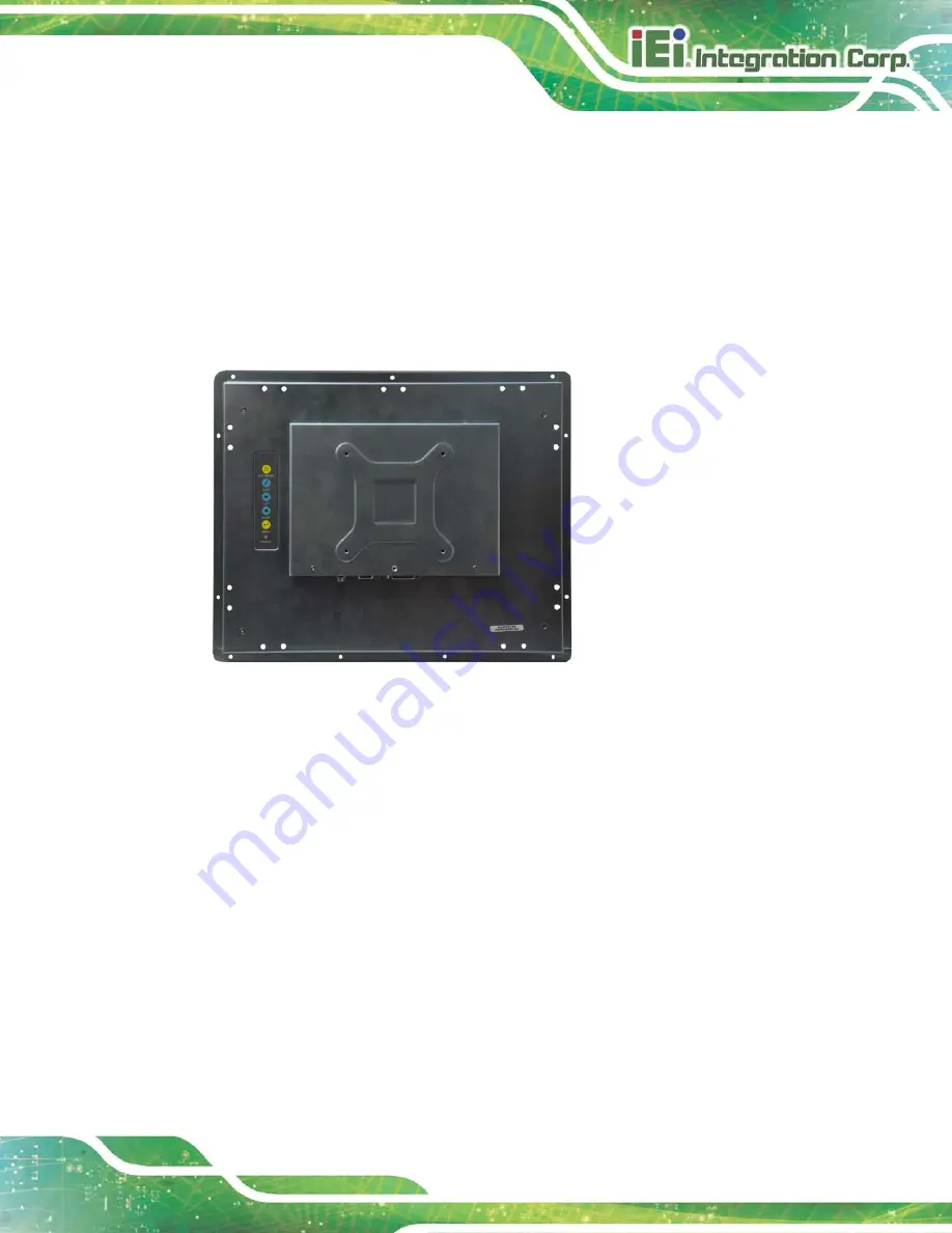
Figure 1-3 shows a typical LCD-KIT-F rear panel. 


Figure 1-3: Typical LCD-KIT-F Rear View 

1.5.3


Co n n e c to rs  

Each LCD-KIT series LCD monitor has a number of interface connectors on the I/O panel 

of the chassis (when viewing the rear panel). 

364H

Figure  1-4  shows a typical LCD-KIT-F 

connector panel. Each model may include or exclude additional connectors. Refer to 

Section 

365H

2.3

  for listings of LCD-KIT-Fs and their connectors. All connectors are fully 

described in 

Section 

366H

5.4

. 

Summary of Contents for LCD-KIT-F Series

Page 1: ...LCD KIT F Page i Us er Manual MODEL LCD KIT F Series 12 1 19 Open Frame LCD Monitor VGA DVI D RoHS Rev 1 00 6 J une 2016 ...

Page 2: ...LCD KIT F Page ii Revis ion Date Version Changes 6 June 2016 1 00 Initial release ...

Page 3: ...ing out of the use or inability to use the product or documentation even if advised of the possibility of such damages This document contains proprietary information protected by copyright All rights are reserved No part of this manual may be reproduced by any mechanical electronic or other means in any form without prior written permission of the manufacturer TRADEMARKS All registered trademarks ...

Page 4: ...tionary messages should be heeded to help reduce the chance of losing data or damaging the product NOTE These messages inform the reader of essential but non critical information These messages should be read carefully as any directions or instructions contained therein can help avoid making mistakes HOT SURFACE This symbol indicates a hot surface that should not be touched without taking care ...

Page 5: ...NTRODUCTION 9 2 2 REAR PANEL 9 2 3 CONNECTOR PANEL 9 2 3 1 Available Connectors 10 2 4 PHYSICAL DIMENSIONS 10 2 4 1 General Physical Dimensions 10 2 4 2 LCD KIT F 12A Physical Dimensions 11 2 4 3 LCD KIT F 15A Physical Dimensions 12 2 4 4 LCD KIT F 17A Physical Dimensions 13 2 4 5 LCD KIT F 19A Physical Dimensions 14 2 5 MOUNTING HOLES 15 3 LCD SPECIFICATIONS 16 3 1 LCD SPECIFICATIONS 17 3 1 1 LCD...

Page 6: ...r for Touchscreen USB_TOUCH1 25 4 2 8 Touchscreen Connector J1 25 4 2 9 VGA Connector VGA2 26 4 2 10 Backlight Voltage Select Jumper JP5 26 4 2 11 LVDS Panel Voltage Select Jumper JP2 26 4 2 12 Power Input Setting Jumper JP4 27 4 2 13 Touchscreen Type Select Jumper JP1 27 5 INSTALLATION 28 5 1 INSTALLATION PRECAUTIONS 29 5 2 UNPACKING 30 5 2 1 Packaging 30 5 2 2 Unpacking Procedure 30 5 2 3 Packin...

Page 7: ... DRIVER 50 7 1 INTRODUCTION 51 7 2 RS 232 OR USB TOUCH SCREEN 51 7 3 TOUCH PANEL DRIVER INSTALLATION 52 7 4 CHANGE THE TOUCH SCREEN INTERFACE 55 7 5 CALIBRATING THE TOUCH SCREEN 55 A REGULATORY COMPLIANCE 58 B SAFETY PRECAUTIONS 62 B 1 SAFETY PRECAUTIONS 63 B 1 1 General Safety Precautions 63 B 1 2 Anti static Precautions 64 B 1 3 Product Disposal 65 B 2 MAINTENANCE AND CLEANING PRECAUTIONS 66 B 2...

Page 8: ... 77 C 4 4 Display Page for analog signal 78 C 4 5 Color Page 79 C 4 6 PIP Page 80 C 4 7 System Page 81 C 4 8 About Page 82 C 5 SMARTOSD FAQ 83 C 5 1 Windows 2000 Installation Failure 83 C 5 2 Vista Installation Failure 83 C 5 3 Model Failure 84 C 5 4 DDC Port Failure 85 D HAZARDOUS MATERIALS DISCLOSURE 86 ...

Page 9: ...22 Figure 5 1 VGA Connector 33 Figure 5 2 DVI D Connector 34 Figure 5 3 12V Power Connector 34 Figure 5 4 3 pin Terminal Block 35 Figure 5 5 RS 232 Touch Panel Connector 35 Figure 5 6 USB Touch Panel Connector 36 Figure 5 7 Mounting Clamps Holder 37 Figure 5 8 Mounting Clamps 37 Figure 5 9 Secure the Mounting Clamps Holders 38 Figure 5 10 Panel Mounting Clamp Position 38 Figure 5 11 Mounting Clamp...

Page 10: ...3 License Agreement 53 Figure 7 4 Initiate Install 54 Figure 7 5 Installation Starts 54 Figure 7 6 Finish Installation 55 Figure 7 7 PenMount Monitor Icon 56 Figure 7 8 PenMount Monitor Popup Menu 56 Figure 7 9 Configuration Screen 56 Figure 7 10 Calibration Initiation Screen 57 Figure 7 11 Calibration Screen 57 ...

Page 11: ...PAD1 Pinouts 24 Table 4 5 Power Input Connector PWR2 Pinouts 25 Table 4 6 RS 232 Connector for Touchscreen RS232_1 Pinouts 25 Table 4 7 USB Connector for Touchscreen USB_TOUCH1 Pinouts 25 Table 4 8 Touchscreen Connector J1 Pinouts 26 Table 4 9 VGA Connector VGA2 Pinouts 26 Table 4 10 Backlight Voltage Select Jumper JP5 Pinouts 26 Table 4 11 LVDS Panel Voltage Select Jumper JP2 Pinouts 26 Table 4 1...

Page 12: ...LCD KIT F Page 1 Chapter 1 1 Introduction ...

Page 13: ... ease of connection with a management computer If remote non attentive control is preferred RS 232 or USB interfaces can be used with customized adapter cables 1 2 Features The LCD KIT F series have the following standard features 12 1 19 open frame architecture for embedded integration Over 350cd m high brightness and 50000hrs MTFB long lifetime panel Analog VGA or digital DVI interfaces support ...

Page 14: ...uch screen RS 232 USB interface R10 LCD KIT F12A TW R10 12 1 600 cd m XGA open frame monitor VGA and DVI D input Resistive touch window RS 232 USB interface R10 LCD KIT F15A TW R10 15 450 cd m XGA open frame monitor VGA and DVI D input Resistive touch window RS 232 USB interface R10 LCD KIT F17A TW R10 17 350 cd m SXGA open frame monitor VGA and DVI D input Resistive touch window RS 232 USB interf...

Page 15: ...clude VGA and DVI 1 5 External Overview The following sections describe the physical layout of the LCD KIT F series LCD monitors 1 5 1 Front View The front of the LCD KIT F series LCD monitor is a flat panel TFT LCD screen attached to a metal chassis 362HFigure 1 2 shows a typical LCD KIT F front view Figure 1 2 Typical LCD KIT F Front View 1 5 2 Rear View The rear of the LCD KIT F series LCD moni...

Page 16: ...nectors Each LCD KIT series LCD monitor has a number of interface connectors on the I O panel of the chassis when viewing the rear panel 364HFigure 1 4 shows a typical LCD KIT F connector panel Each model may include or exclude additional connectors Refer to Section 365H2 3 for listings of LCD KIT Fs and their connectors All connectors are fully described in Section 366H5 4 ...

Page 17: ...tio 700 1 800 1 800 1 1000 1 Display Color 16 2M 16 2M 16 7M 16 7M Pixel Pitch mm 0 24 0 297 0 264 0 294 Viewing Angle H V 160 140 160 150 170 160 170 160 AD Board AV 60381 Input Interface Analog VGA DVI D RS 232 USB Optional for Touch Touchscreen controller Resistive type 5 wire single touch Penmount 6000 or Projected capacitive 2 point touch EETI EXC7200 Assembly by adhesive tape OSD function 5 ...

Page 18: ...on condensing Input Voltage 12VDC 9 36V Optional with LCD KIT F 936160 R10 Construction Material sheet metal rear cover SPCC Mounting Panel Mount Rear Mount VESA 100 1 7 Certifications All LCD KIT F series LCD monitor models comply with the following international standards RoHS For a more detailed description of these standards please refer to Appendix D ...

Page 19: ...LCD KIT F Page 8 Chapter 2 2 Mechanical Overview ...

Page 20: ...eries LCD monitor have an OSD control panel located vertically along the left side of the rear panel LCD KIT F12A LCD KIT F15A LCD KIT F17A LCD KIT F19A 370HFigure 2 1 shows the location of the rear panel OSD controls Figure 2 1 Rear Panel 2 3 Connector Panel All external peripheral interface connectors are located on the rear panel of the LCD KIT F series LCD monitor The following sections descri...

Page 21: ...SB connector Optional for Touch 2 4 Phys ical Dimens ions The following sections describe the physical dimensions for each model of the LCD KIT F series LCD monitor 2 4 1 General Phys ical Dimens ions General physical dimensions for the LCD KIT F series LCD monitors are shown in 372HTable 2 1 Model Width mm Height mm Depth mm LCD KIT F12A 323 8 263 8 40 3 LCD KIT F15A 380 1 304 6 43 2 LCD KIT F17A...

Page 22: ...LCD KIT F Page 11 2 4 2 LCD KIT F 12A Phys ical Dimens ions The physical dimensions of the LCD KIT F 12A are shown in 375HFigure 2 5 Figure 2 2 LCD KIT F 12A Physical Dimensions millimeters ...

Page 23: ...LCD KIT F Page 12 2 4 3 LCD KIT F 15A Phys ical Dimens ions The physical dimensions of the LCD KIT F 15A are shown in 375HFigure 2 3 Figure 2 3 LCD KIT F 15A Physical Dimensions millimeters ...

Page 24: ...LCD KIT F Page 13 2 4 4 LCD KIT F 17A Phys ical Dimens ions The physical dimensions of the LCD KIT F 17A are shown in 375HFigure 2 4 Figure 2 4 LCD KIT F 17A Physical Dimensions millimeters ...

Page 25: ...LCD KIT F Page 14 2 4 5 LCD KIT F 19A Phys ical Dimens ions The physical dimensions of the LCD KIT F 19A are shown in 375HFigure 2 5 Figure 2 5 LCD KIT F 19A Physical Dimensions millimeters ...

Page 26: ...located on the rear panel 380HTable 2 2 details the number of mounting holes for each model of the LCD KIT series LCD monitor Refer to Section 381H2 4 for more information Model Number of Mounting Holes LCD KIT F12A 20 LCD KIT F15A 20 LCD KIT F17A 20 LCD KIT F19A 20 Table 2 2 Mounting Holes ...

Page 27: ...LCD KIT F Page 16 Chapter 3 3 LCD Specifications ...

Page 28: ... LED Brightnes s cd m2 600 Res olution 1024 x 768 Screen Scale 4 3 Life Time 50000H Contras t Ratio 700 1 View Angle H V 160 140 Interface 1ch LVDS Operating Temperature 30 C 80 C Active Area mm 245 75 x 184 32 Pixel Pitch mm 0 24 Mode Normal White Number of Colors 16 2M Supply Voltage V 3 3 Table 3 1 LCD KIT F12A LCD Specifications 3 1 2 LCD KIT F15A LCD Specifications The table below lists the L...

Page 29: ...ea mm 304 128 x 228 096 Pixel Pitch mm 0 297 Dis play Mode Normal White Dis play Color 16 2M Supply Voltage V 3 3 Table 3 2 LCD KIT F15A LCD Specifications 3 1 3 LCD KIT F17A LCD Specifications The table below lists the LCD KIT F17A LCD specifications Items LCD KIT F17A Size 17 Backlight LED Brightnes s cd m2 350 Res olution 1280 x 1024 Screen Scale 4 3 Life Time 50000H Contras t Ratio 800 1 View ...

Page 30: ...ions 3 1 4 LCD KIT F19A LCD Specifications The table below lists the LCD KIT F19A LCD specifications Items LCD KIT F19A Size 19 Backlight LED Brightnes s cd m2 350 Res olution 1280 x 1024 Screen Scale 4 3 Life Time 50000H Contras t Ratio 1000 1 View Angle H V 170 160 Active Area mm 304 1 x 228 1 Pixel Pitch mm 0 294 Dis play Mode Normal White Dis play Color 16 7M Supply Voltage V 3 3 Table 3 4 LCD...

Page 31: ...Voltage 12 V Output Voltage 3 A Output Watts 36W Efficiency 86 Operating Temperature 0 C 40 C Storage Temperature 20 C 70 C Table 3 5 Power Adapter Specifications 3 3 9 36V DC Module 382HTable 3 6 lists the 9 36V DC module specifications Model LCD KIT F 936160 R10 Input Voltage Range 9 V 36 V Output Voltage 12 V Output Watts 60W Table 3 6 9 36V DC Module Specifications ...

Page 32: ...LCD KIT F Page 21 Chapter 4 4 AD Board ...

Page 33: ...lso indicated in the diagrams below The connector pinouts for these connectors are listed in the following sections Figure 4 1 AV 60381 AD Board Layout Diagram 4 2 1 AV 60381 Peripheral Interface Connectors 527HTable 4 1 shows a list of the peripheral interface connectors on the AV 60381 AD board Pinouts of the connectors that are used in the LCD KIT F can be found in the following sections Connec...

Page 34: ...6 pin wafer p 1 25 mm JSPI1 USB connector for touchscreen 4 pin wafer p 1 25 mm USB_TOUCH1 Touchscreen connector 9 pin wafer p 1 25 mm J1 VGA connector 10 pin box header p 2 00 mm VGA2 J umper Type Label Backlight voltage select jumper 6 pin header p 2 54 mm JP5 LVDS panel voltage select jumper 6 pin header p 2 54 mm JP2 Power input setting jumper 6 pin header p 2 54 mm JP4 Touchscreen type select...

Page 35: ...C 12 A3M_C 13 GND 14 GND 15 A4P_C 16 A4M_C 17 A5P_C 18 A5M_C 19 A6P_C 20 A6M_C 21 CLK2P_C 22 CLK2M_C 23 A7P_C 24 A7M_C 25 GND 26 GND 27 VCC 28 VCC 29 VCC 30 VCC Table 4 3 LVDS Connector LVDS1 Pinouts 4 2 4 OSD Keypad Connector KEYPAD1 PIN NO DESCRIPTION PIN NO DESCRIPTION 1 5V_OSD NC 2 12V NC 3 Left 4 Auto 5 Right 6 Power 7 Menu 8 Led_GREED UP 9 Down NC 10 Led_RED 11 GND 12 3 3V_DVDD NC Table 4 4 ...

Page 36: ...or Touchs creen RS232_1 PIN NO DESCRIPTION 1 NDSR 2 NRX 3 NRTS 4 NTX 5 NDTR 6 GND Table 4 6 RS 232 Connector for Touchscreen RS232_1 Pinouts 4 2 7 USB Connector for Touchs creen USB_TOUCH1 PIN NO DESCRIPTION 1 VCC_TOUCH 2 D2F 3 D2F 4 GND Table 4 7 USB Connector for Touchscreen USB_TOUCH1 Pinouts 4 2 8 Touchs creen Connector J 1 PIN NO DESCRIPTION PIN NO DESCRIPTION 1 X 2 X 3 Y 4 SENSE 5 X 6 X ...

Page 37: ...5 BLUE 6 GND 7 H SYNC 8 GND 9 V SYNC 10 GND Table 4 9 VGA Connector VGA2 Pinouts 4 2 10 Backlight Voltage Select J umper J P5 DESCRIPTION Short 1 2 3 3 V Short 3 4 5 V Short 5 6 12 V Table 4 10 Backlight Voltage Select Jumper JP5 Pinouts 4 2 11 LVDS Panel Voltage Select J umper J P2 DESCRIPTION Short 1 2 3 3 V for 6 5 and 8 Short 3 4 5 V Short 5 6 NC Table 4 11 LVDS Panel Voltage Select Jumper JP2...

Page 38: ...er jack PRW1 Short 3 5 4 6 Input with external connector external power module is needed Table 4 12 Power Input Setting Jumper JP4 Pinouts 4 2 13 Touchs creen Type Select J umper J P1 DESCRIPTION 1 5 wire touchscreen 2 4 wire 8 wire touchscreen Table 4 13 Touchscreen Type Select Jumper JP1 Pinouts ...

Page 39: ...LCD KIT F Page 28 Chapter 5 5 Ins tallation ...

Page 40: ...ers Mounting Since the monitor may weigh up to 10 kg not including a swing arm or other accessories please ensure at least two people assist with mounting the monitor Air Circulation Make sure there is sufficient air circulation when installing the monitor The monitor s cooling vents must not be obstructed by any objects Blocking the vents can cause overheating of the monitor Leave at least 5 cm o...

Page 41: ... front side LCD screen has a protective plastic cover stuck to the screen Only remove the plastic cover after the LCD KIT F series LCD monitor has been properly installed This ensures the screen is protected during the installation process Step 1 Use box cutters a knife or a sharp pair of scissors that seals the top side of the external second box Step 2 Open the external second box Step 3 Use box...

Page 42: ...Item Image Standard 1 LCD KIT series LCD monitor 1 AC power adapter P N 63040 010036 121 RS 1 AC power cable 1 USB cable for Touch P N 32001 006100 200 RS 1 VGA cable P N 32000 036200 RS 1 Utility CD Optional RS 232 cable for Touch P N 32005 001100 200 RS DVI cable P N 32000 086600 RS Panel mount kit P N FPK 01 R10 P N FPK 02 R10 ...

Page 43: ...not damage the LCD screen on the front of the LCD KIT F series LCD monitor 5 4 Connectors 390HTable 5 1 lists the rear panel connectors for the LCD KIT F series LCD monitors LCD KIT DVI D VGA 12V DC J ack 9 36V Terminal Block USB RS 232 LCD KIT F12A R10 Yes Yes Yes Optional No No LCD KIT F15A R10 Yes Yes Yes Optional No No LCD KIT F17A R10 Yes Yes Yes Optional No No LCD KIT F19A R10 Yes Yes Yes Op...

Page 44: ...or Use the rear panel standard 15 pin female VGA connector to connect the LCD monitor to the system graphics interface Pin Description Pin Description Pin Description 1 RED 6 GROUND 11 NC 2 GREEN 7 GROUND 12 DDCDAT 3 BLUE 8 GROUND 13 HSYNC 4 NC 9 NC 14 VSYNC 5 GROUND 10 GROUND 15 DDCCLK Table 5 2 VGA Connector Pinouts Figure 5 1 VGA Connector 5 4 2 DVI D Connector The 24 pin Digital Visual Interfa...

Page 45: ...S Clock 12 NC 24 TMDS Clock Table 5 3 DVI D Connector Pinouts Figure 5 2 DVI D Connector 5 4 3 12V Power Connector Use the rear panel 12V DC jack to connect the monitor to a power source Figure 5 3 12V Power Connector 5 4 4 9 V 36 V Terminal Block Optional Connect the leads of 9 V 36 V DC power supply into the terminal block Make sure that the power and ground wires are attached to the correct soc...

Page 46: ...he rear panel standard RS 232 DB 9 female touch panel connector to connect the monitor to the system graphics interface PIN DESCRIPTION PIN DESCRIPTION 1 N A 6 NDSR 2 NRX 7 NRTS 3 NTX 8 N A 4 NDTR 9 N A 5 GND Table 5 4 RS 232 Touch Panel Connector Pinouts Figure 5 5 RS 232 Touch Panel Connector ...

Page 47: ... 5 6 USB Touch Panel Connector 5 5 Mounting the LCD KIT F Series LCD Monitor 5 5 1 Panel Mounting Each model of the LCD KIT F series LCD monitor has a series of mounting slots located on the top side and bottom panels for mounting the monitor to a panel 540HTable 2 2 lists the number of mounting clamps and holders required to mount the monitor to a panel Model Mounting Clamps Clamp Holders LCD KIT...

Page 48: ...ount the monitor Step 2 Cut out a section of the panel that corresponds to the rear panel dimensions of the monitor Take care that the panel section that is cut out is smaller than the overall size of the metal frame that surrounds the monitor but just large enough for the rear panel of the monitor to fit through Step 3 Secure the mounting clamps holders to the corresponding holes on the rear of t...

Page 49: ...inum frame is flush against the panel Step 5 Insert the panel mounting clamps into the pre formed holes of the clamp holders Figure 5 10 Panel Mounting Clamp Position Step 6 Tighten the screws that pass through the panel mounting clamps until the plastic caps at the front of all the screws are firmly secured to the panel ...

Page 50: ...LCD KIT F Page 39 Figure 5 11 Mounting Clamps Holder Dimensions Figure 5 12 Ultra Set Plate Dimensions Figure 5 13 Bolt Dimensions ...

Page 51: ...LCD KIT F Page 40 Figure 5 14 Steering Button Dimensions ...

Page 52: ...LCD KIT F Page 41 Chapter 6 6 On Screen Dis play OSD Controls ...

Page 53: ...F Press this button to turn on or turn off the LCD screen AUTO Press this button to automatically adjust the screen When inside a menu press this button to confirm the selection of the item LEFT Press this button to decrease the value or to scroll up from one selected item to another RIGHT Press this button to increase the value or to scroll down from one selected item to another MENU Press this b...

Page 54: ...0 to 100 Contrast 0 to 100 Sharpness 4 to 4 Color Auto Color temp 5000K 6500K 9300K User Reset Display Auto Adjust Phase 0 to 100 Clock 0 to 100 Display Position Display Modes Gamma off Gamma 2 2 System Input Display Port VGA DVI HDMI autoscan OSD Setting Timer 10sec 30sec 60sec Rotation 0 90 180 270 Position Transparency 0 to 100 Information Reset Table 6 2 OSD Menu Structure ...

Page 55: ...ness of screen This function adjusts the offset value of ADC Setting this value too high or too low will affect the quality of image Contrast This function adjusts the gain value of ADC Adjusting this value too high or too low will worsen the quality of image Sharpness Adjusts the sharpness level This option softens the edges around objects on the screen Color Provides options for color settings F...

Page 56: ...auto Automatically adjusts the color settings Color temp This item allows adjustment of the following items 5000k NTSC standard Kelvin 6500k NTSC standard Kelvin 9300k NTSC standard Kelvin User This item allows fine tuning the balance among Red Green and Blue color hues if images look garish or unrealistic ...

Page 57: ...6 4 Display Menu Auto Adjust Automatically adjusts the LCD screen position Phase Adjusts the input signal analog only Clock Adjusts the dot clock position Display Position Adjusts the horizontal and vertical position of the display screen Display Mode This item allows adjustment of the Gamma ...

Page 58: ...ws selection of input device to use Figure 6 6 OSD Settings Provides options for OSD configuration Figure 6 7 Information Provides information on the LCD monitor such as firmware version release date and input resolution Reset Restores the default OSD settings Note that this will restore all default display settings ...

Page 59: ... 6 6 Figure 6 6 Input Options Input options are described below Display Port This item sets the input device to display port VGA This item sets the input device to VGA HDMI This item sets the input device to HDMI autoscan Selects the input device to use automatically ...

Page 60: ...SD settings are described below Timer Determines how many seconds the OSD screen stays on screen before it disappears when OSD is left unattended Rotation Adjusts the OSD rotation angle on the screen Position Adjusts the OSD position on the screen Transparency Adjust the transparency of the OSD menu background ...

Page 61: ...LCD KIT F Page 50 Chapter 7 7 Software Driver ...

Page 62: ...ft Windows XP o Microsoft Windows 2003 o Microsoft Windows 2008 o Microsoft Windows Vista o Microsoft Windows 7 Microsoft Windows CE versions o Microsoft Windows CE 4 2 o Microsoft Windows CE 5 0 o Microsoft Windows CE 6 0 Linux Kernel 2 6 DOS Driver installation is described below 7 2 RS 232 or USB Touch Screen Before installing the driver connect the LCD KIT F monitor to the motherboard The LCD ...

Page 63: ...with a USB cable or an RS 232 null cable Also make sure the VGA connector on the system is connected to the VGA connector on the bottom of the monitor To install the touch panel driver for the LCD KIT F please follow the instructions below Step 7 Connect the LCD KIT F monitor to the single board computer See above Step 8 Install the driver CD Install the driver CD into the system to which the LCD ...

Page 64: ... in Figure 7 1 Step 11 The Welcome screen in Figure 7 2 appears Figure 7 2 Welcome Screen Step 12 Click Next to continue Step 13 The license agreement in Figure 7 3 appears Accept the terms of the agreement by clicking I Agree Figure 7 3 License Agreement ...

Page 65: ...gure 7 4 Click Install Figure 7 4 Initiate Install Step 15 The installation of the program begins See Figure 7 5 Figure 7 5 Installation Starts Step 16 When the installation is complete the complete screen appears See Figure 7 6 To complete the installation process click Finish ...

Page 66: ...e interface cable i e remove the RS 232 cable or the USB cable Step 19 Install the new cable i e install the USB cable or the RS 232 cable Step 20 Reinstall the driver CD as described above Step 0 7 5 Calibrating the Touch Screen To calibrate the touch screen cursor with the motion of the touch screen pen or finger please follow the steps below Step 1 Make sure the system is properly connected thr...

Page 67: ...e screen Figure 7 7 PenMount Monitor Icon Step 4 Click the icon A pop up menu appears See Figure 7 8 Figure 7 8 PenMount Monitor Popup Menu Step 5 Click Control Panel in the pop up menu shown in Figure 7 8 Step 6 The configuration screen in Figure 7 9 appears Figure 7 9 Configuration Screen ...

Page 68: ...pears Step 9 Select the Standard Calibration button as shown in Figure 7 10 Figure 7 10 Calibration Initiation Screen Step 10 The calibration screen in is shown See Figure 7 11 Figure 7 11 Calibration Screen Step 11 Follow the instructions The user is asked touch the screen at five specified points after which the screen is calibrated Step 0 ...

Page 69: ...LCD KIT F Page 58 396H Appendix A A Regulatory Compliance ...

Page 70: ...at this equipment is in compliance with the essential requirements and other relevant provisions of Directive 2014 53 EU Български Bulgarian IEI Integration Corp декларира че този оборудване е в съответствие със съществените изисквания и другите приложими правила на Директива 2014 53 EU Česky Czech IEI Integration Corp tímto prohlašuje že tento zařízení je ve shodě se základními požadavky a dalším...

Page 71: ...dispositions pertinentes de la directive 2014 53 EU Italiano Italian IEI Integration Corp dichiara che questo apparecchio è conforme ai requisiti essenziali ed alle altre disposizioni pertinenti stabilite dalla direttiva 2014 53 EU Latviski Latvian IEI Integration Corp deklarē ka iekārta atbilst būtiskajām prasībām un citiem ar to saistītajiem noteikumiem Direktīvas 2014 53 EU Lietuvių Lithuanian ...

Page 72: ...in conformitate cu cerinţele esenţiale şi cu celelalte prevederi relevante ale Directivei 2014 53 EU Slovensko Slovenian IEI Integration Corp izjavlja da je ta opreme v skladu z bistvenimi zahtevami in ostalimi relevantnimi določili direktive 2014 53 EU Slovensky Slovak IEI Integration Corp týmto vyhlasuje že zariadenia spĺňa základné požiadavky a všetky príslušné ustanovenia Smernice 2014 53 EU S...

Page 73: ...LCD KIT F Page 62 Appendix B B Safety Precautions ...

Page 74: ...e risk of electric shock make sure power cord is unplugged from wall socket To fully disengage the power to the unit please disconnect the power cord from the AC outlet Refer servicing to qualified service personnel The AC outlet shall be readily available and accessible Do not apply voltage levels that exceed the specified voltage range Doing so may cause fire and or an electrical shock Use a pow...

Page 75: ...g the LCD KIT F Dry climates are especially susceptible to ESD It is therefore critical that whenever the LCD KIT F is opened and any of the electrical components are handled the following anti static precautions are strictly adhered to Wear an anti static wristband Wearing a simple anti static wristband can help to prevent ESD from damaging any electrical component Self grounding Before handling ...

Page 76: ...assified as electronic device in terms of the European Directive 2012 19 EU WEEE and must not be disposed of as domestic garbage EU wide legislation as implemented in each Member State requires that waste electrical and electronic products carrying the mark left must be disposed of separately from normal household waste This includes monitors and electrical accessories such as signal cables or pow...

Page 77: ...h a piece of soft dry cloth or a slightly moistened cloth The interior of the device does not require cleaning Keep fluids away from the device interior Be cautious of all small removable components when vacuuming the device Never drop any objects or liquids through the openings of the device Be cautious of any possible allergic reactions to solvents or chemicals used when cleaning the device Avoi...

Page 78: ...acuum specifically designed for computers is one of the best methods of cleaning the device Dust and dirt can restrict the airflow in the device and cause its circuitry to corrode Cotton swabs Cotton swaps moistened with rubbing alcohol or water are excellent tools for wiping hard to reach areas Foam swabs Whenever possible it is best to use lint free swabs such as foam swabs for cleaning ...

Page 79: ...LCD KIT F Page 68 Appendix C C s martOSD ...

Page 80: ...en position size color gain to be read and changed over normal video cable VGA or DVI C 2 Pre ins tallation Notice Before installing smartOSD software please make sure one of the following operating systems is installed Windows 95 Windows NT 4 0 Windows 98 Windows 2000 Windows 2003 Windows XP Windows Vista Windows 7 C 3 s martOSD Ins tallation Connect the LCD KIT F to a host computer Insert the CD...

Page 81: ...lick Next to continue Step 5 The Folder Select screen in 592HFigure C 2 appears Figure C 2 smartOSD Folder Select Screen Step 6 Select the installation folder in 593HFigure C 2 shown above Step 7 Click Next to continue Step 8 The screen in 594HFigure C 3 appears ...

Page 82: ...allation by clicking Next in the screen above Step 10 The program starts to install and the progress bar shown in 595HFIgure C 4 appears Figure C 4 smartOSD Installation Progress Step 11 When the installation is complete the Complete Installation screen in 596HFi F Figure C 5 appears ...

Page 83: ...above Step 13 After quick setup is complete the IEI smartOSD wizard logo appears on the desktop as shown in the screen below Step 14 To access the smartOSD click the smartOSD wizard logo Step 0 C 4 Software Illus tration The table below shows the smartOSD menu structure for all IEI LCD monitors ...

Page 84: ...DID EDID contains basic information about the monitor and its capabilities Image Brightness Contrast Sharpness Display Auto Adjust Phase Clock Color Auto Color User Red Gain User Green Gain User Blue Gain Color Temperature Gamma disabled in the DM F Series PIP PIP disabled in the DM F Series PIP Source Input disabled in the DM F Series PIP Size disabled in the DM F Series System Monitor Power Cont...

Page 85: ...rightness disabled in the DM F Series Main Source Input YPbPr S Video and CVBS disabled Volume disabled in the DM F Series Factory Presets OSD Lock OSD Unlock Mute disabled in the DM F Series Table C 1 SmartOSD Menu Structure ...

Page 86: ...LCD KIT F Page 75 C 4 1 Manage Page Figure C 6 Manage Page ...

Page 87: ...LCD KIT F Page 76 C 4 2 EDID Page Figure C 7 EDID Page ...

Page 88: ...LCD KIT F Page 77 C 4 3 Image Page Figure C 8 Image Page ...

Page 89: ...LCD KIT F Page 78 C 4 4 Dis play Page for analog s ignal Figure C 9 Display Page ...

Page 90: ...LCD KIT F Page 79 C 4 5 Color Page Figure C 10 Color Page ...

Page 91: ...LCD KIT F Page 80 C 4 6 PIP Page NOTE The functions in the PIP page are only available in the MLCD KIT Series and AFOLUX Series monitors Figure C 11 PIP Page ...

Page 92: ...e NOTE Some of the functions in the System Page are only available to some of the IEI LCD series as following Auto Brightness SRM MLCD KIT and AFOLUX series only Main Source Input MLCD KIT and AFOLUX series only Volume AFOLUX series only Mute AFOLUX series only ...

Page 93: ...LCD KIT F Page 82 C 4 8 About Page Figure C 13 About Page ...

Page 94: ...ns tallation Failure Installation fails under Windows 2000 and shows the following image Figure C 14 DLL Missing Solution Download and install service pack Windows Installer 3 1 C 5 2 Vis ta Ins tallation Failure Installation fail under Vista while showing following image Figure C 15 Windows Vista Error ...

Page 95: ...as the administrator authority Figure C 16 Install as Administrator C 5 3 Model Failure The Model Fail error message shown below appears Figure C 17 Firmware Incompatibility Solution SmartOSD only supports firmware version 2 0 and following versions ...

Page 96: ...e Solutions Check VGA or HDMI cable Check an IEI monitor is being used Make sure the version is version 2 3 for the AFOLUX MDM series and version 1 5 for the DM ISDM TDM SRM LCD KIT series that have the SmartOSD functions Check if the OSD control status is busy A busy signal may cause the signal message for a short time ...

Page 97: ...LCD KIT F Page 86 Appendix D D Hazardous Materials Dis clos ure ...

Page 98: ...ese components will be separately marked Please refer to the following table Part Name Toxic or Hazardous Substances and Elements Lead Pb Mercury Hg Cadmium Cd Hexavalent Chromium CR VI Polybrominated Biphenyls PBB Polybrominated Diphenyl Ethers PBDE Housing O O O O O O Display O O O O O O Printed Circuit Board O O O O O O Metal Fasteners O O O O O O Cable Assembly O O O O O O Fan Assembly O O O O...

Page 99: ...些元 件将会单独标示出来 部件名称 有毒有害物质或元素 铅 Pb 汞 Hg 镉 Cd 六价铬 CR VI 多溴联苯 PBB 多溴二苯 醚 PBDE 壳体 O O O O O O 显示 O O O O O O 印刷电路板 O O O O O O 金属螺帽 O O O O O O 电缆组装 O O O O O O 风扇组装 O O O O O O 电力供应组装 O O O O O O 电池 O O O O O O O 表示该有毒有害物质在该部件所有物质材料中的含量均在 SJ T 11363 2006 现由 GB T 26572 2011 取代 标准规定的限量要求以下 X 表示该有毒有害物质至少在该部件的某一均质材料中的含量超出 SJ T 11363 2006 现由 GB T 26572 2011 取代 标准规定的限量要求 ...

Reviews: