IVS-200-ULT2 Embedded System
Page 36
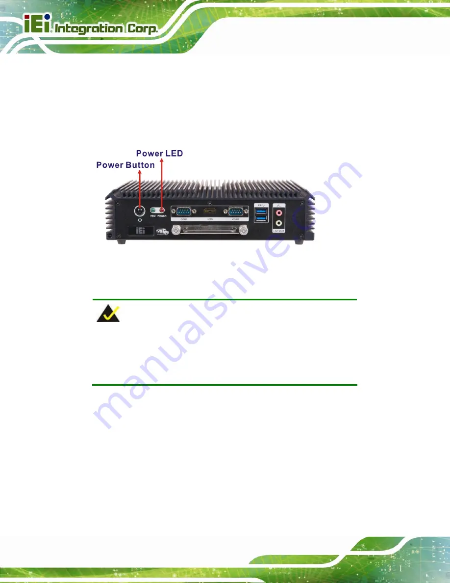
3.12.3 Power-on Procedure
To power-on the IVS-200-ULT2 please follow the steps below:
Step 1:
Connect the power source to the power input terminal block.
Step 2:
Push the power button until the power LED lights on (
Step 0:
Figure 3-29: Power Button and Power LED
3.13 Driver Installation
NOTE:
The content of the CD may vary throughout the life cycle of the product
and is subject to change without prior notice. Visit the IEI website or
contact technical support for the latest updates.
All the drivers for the IVS-200-ULT2 are on the utility CD that came with the system. The
following drivers can be installed on the system:
Chipset
Graphics
LAN
Audio
USB
3.0
Summary of Contents for IVS-200-ULT2
Page 13: ...IVS 200 ULT2 Embedded System Page 1 Chapter 1 1 Introduction ...
Page 22: ...IVS 200 ULT2 Embedded System Page 10 Chapter 2 2 Unpacking ...
Page 25: ...IVS 200 ULT2 Embedded System Page 13 VESA MIS D 100 wall mount kit Table 2 2 Optional Items ...
Page 26: ...IVS 200 ULT2 Embedded System Page 14 Chapter 3 3 Installation ...
Page 50: ...IVS 200 ULT2 Embedded System Page 38 Chapter 4 4 BIOS ...
Page 85: ...IVS 200 ULT2 Embedded System Page 73 Chapter 5 5 Troubleshooting and Maintenance ...
Page 90: ...IVS 200 ULT2 Embedded System Page 78 Chapter 6 6 Interface Connectors ...
Page 97: ...IVS 200 ULT2 Embedded System Page 85 Appendix A A Regulatory Compliance ...
Page 102: ...IVS 200 ULT2 Embedded System Page 90 B Safety Precautions Appendix B ...
Page 108: ...IVS 200 ULT2 Embedded System Page 96 Appendix C C BIOS Menu Options ...
Page 111: ...IVS 200 ULT2 Embedded System Page 99 Appendix D D Watchdog Timer ...
Page 114: ...IVS 200 ULT2 Embedded System Page 102 Appendix E E Hazardous Materials Disclosure ...


