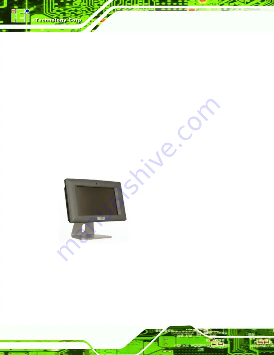
IOVU-570M Panel PC
Page 30
Step 17:
Align the retention screw holes on the mounting arm interface with those on the
IOVU-570M.
Step 18:
Secure the IOVU-570M to the interface pad by inserting four retention screws
through the bottom of the mounting arm interface pad and into the IOVU-570M.
S
te
p
0
:
4.4.4 Stand Mounting
The IOVU-570M has Video Electronics Standards Association (VESA) standard mounting
holes tapped into the rear panel. The monitor stand mounting plate has a matching VESA
hole pattern. To mount the IOVU onto a stand, please follow the steps below.
Step 1:
Line up the threaded holes on the monitor rear panel with the screw holes on the
monitor stand mounting plate.
Step 2:
Secure the monitor to the stand with the supplied retention screws
(Figure 4-16).
Step 0:
Figure 4-16: Stand Mounting
4.5 Software
The IOVU-570M comes with a pre-installed Windows CE 5.0 or Linux 2.6.x operating
system and a rich software application development kit. For information about configuring
the operating system, adding remote management tools or additional software and
drivers, refer to the user manuals on IEI IOVU Utility CD that came with the IOVU-570M.
The IOVU includes the following software:
Summary of Contents for IOVU-570M
Page 2: ...IOVU 570M Panel PC Page ii Revision Date Version Changes 24 June 2009 1 00 Initial release ...
Page 8: ......
Page 9: ...IOVU 570M Panel PC Page 1 Chapter 1 1 Introduction ...
Page 13: ...IOVU 570M Panel PC Page 5 Chapter 2 2 Detailed Specifications ...
Page 18: ...IOVU 570M Panel PC Page 10 Chapter 3 3 Unpacking ...
Page 23: ...IOVU 570M Panel PC Page 15 Chapter 4 4 Installation ...
Page 40: ...IOVU 570M Panel PC Page 32 Appendix A A Certifications ...
Page 42: ...IOVU 570M Panel PC Page 34 Appendix B B Safety Precautions ...
Page 46: ...IOVU 570M Panel PC Page 38 Appendix C C Hazardous Materials Disclosure ...


