IEI Technology IMBA-C2060 User Manual Download Page 102


IMBA-C2060 ATX Motherboard

Page 86 

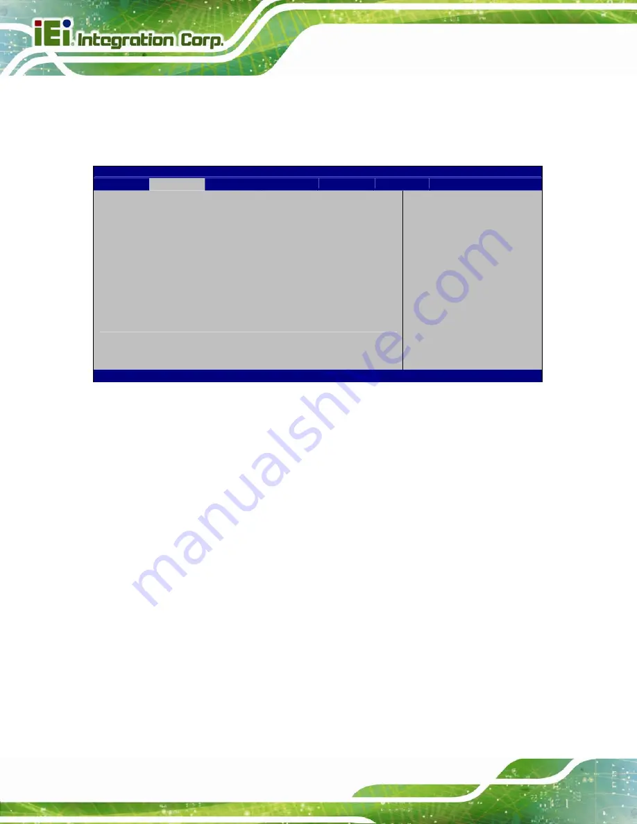
5.3.7 Super IO Configuration 

Use the 

Super IO Configuration

 menu (

BIOS Menu 10

) to set or change the 

configurations for the FDD controllers, parallel ports and serial ports. 

Aptio Setup Utility – Copyright (C) 2011 American Megatrends, Inc. 


Advanced 


Super IO Configuration 
 
Super IO Chip 

Fintek F81866 

> Serial Port 1 Configuration 
> Serial Port 2 Configuration 
> Serial Port 3 Configuration 
> Serial Port 4 Configuration 
> Serial Port 5 Configuration 
> Serial Port 6 Configuration 
 
Power Saving Function 

[Disabled] 

 
Set Parameters of Serial 
Port 1 (COMA) 
 
 
--------------------- 

ÅÆ

: Select Screen 


: Select Item 

Enter 

Select 

+  -   Change  Opt. 
F1 General 

Help 

F2 Previous 

Values 

F3 Optimized 

Defaults

F4 

Save & Exit 

ESC Exit 

Version 2.11.1210. Copyright (C) 2011 American Megatrends, Inc. 

BIOS Menu 10: Super IO Configuration 

Î


Power Saving Function [Disabled] 

Use the 

Power Saving Function

 BIOS option to enable or reduce power consumption in 

the S5 state. When enabled, the system can only be powered-up using the power button.   

Î


Disabled D

EFAULT


Power saving function support disabled 

Î


Enabled  

Power saving function support enabled 

Summary of Contents for IMBA-C2060

Page 1: ...l MODEL IMBA C2060 ATX LGA1155 Motherboard for Intel Core i3 Quad Dual Core CPU Intel C206 Chipset DDR3 VGA DVI HDMI Dual Intel PCIe GbE Intel AMT 7 0 Support Two USB 3 0 Ports Five COM Ports Two SATA...

Page 2: ...R20 version 9 November 2012 1 03 Added Appendix F Intel Matrix Storage Manager 9 September 2011 1 02 Modified Section4 3 1 AT ATX Power Select Jumper Added Section 4 6 Intel AMT Setup Procedure Added...

Page 3: ...ges arising out of the use or inability to use the product or documentation even if advised of the possibility of such damages This document contains proprietary information protected by copyright All...

Page 4: ...L ITEMS 12 3 CONNECTORS 14 3 1 PERIPHERAL INTERFACE CONNECTORS 15 3 1 1 IMBA C2060 Layout 15 3 1 2 Peripheral Interface Connectors 16 3 1 3 External Interface Panel Connectors 17 3 2 INTERNAL PERIPHER...

Page 5: ...0 3 2 25 USB Connectors 41 3 3 EXTERNAL PERIPHERAL INTERFACE CONNECTOR PANEL 43 3 3 1 Audio Connector 43 3 3 2 Ethernet and USB Connector 44 3 3 3 HDMI Port Connector 45 3 3 4 Keyboard Mouse Connector...

Page 6: ...1 Starting Setup 73 5 1 2 Using Setup 73 5 1 3 Getting Help 74 5 1 4 Unable to Reboot after Configuration Changes 74 5 1 5 BIOS Menu Bar 74 5 2 MAIN 75 5 3 ADVANCED 76 5 3 1 ACPI Settings 77 5 3 2 Tru...

Page 7: ...ATION 131 6 8 INTEL AMT DRIVER AND APPLICATION 133 6 8 1 Intel Management Engine Components Installation 133 6 8 2 Intel IT Director Application Installation 137 A BIOS OPTIONS 144 B ONE KEY RECOVERY...

Page 8: ...3 ASSEMBLY LANGUAGE SAMPLES 181 D 3 1 Enable the DIO Input Function 181 D 3 2 Enable the DIO Output Function 182 E WATCHDOG TIMER 183 F INTEL MATRIX STORAGE MANAGER 186 F 1 INTRODUCTION 187 F 1 1 Pre...

Page 9: ...nector Location 26 Figure 3 10 Front Panel Connector Location 27 Figure 3 11 I2C Connector Location 28 Figure 3 12 Keyboard Mouse Connector Location 29 Figure 3 13 Parallel Port Connector Location 30...

Page 10: ...ake on LAN Connector Pinout Locations 61 Figure 4 11 SATA Drive Cable Connection 62 Figure 4 12 SATA Power Drive Connection 62 Figure 4 13 Audio Connector 63 Figure 4 14 DVI Connector 64 Figure 4 15 H...

Page 11: ...132 Figure 6 26 USB 3 0 Driver Update Complete 133 Figure 6 27 Intel ME Driver Welcome Screen 134 Figure 6 28 Intel ME Driver License Agreement 135 Figure 6 29 Intel ME Driver Read Me File 135 Figure...

Page 12: ...162 Figure B 18 Image Creation Confirmation 163 Figure B 19 Image Creation Process 163 Figure B 20 Image Creation Complete 163 Figure B 21 Press Any Key to Continue 164 Figure B 22 Partitions for Lin...

Page 13: ...ts 26 Table 3 10 Front Panel Connector Pinouts 27 Table 3 11 I2C Connector Pinouts 28 Table 3 12 Keyboard Mouse Connector Pinouts 29 Table 3 13 Parallel Port Connector Pinouts 30 Table 3 14 SATA 3Gb s...

Page 14: ...outs 47 Table 3 30 VGA Connector Pinouts 47 Table 3 31 DVI Connector Pinouts 48 Table 4 1 Jumpers 58 Table 4 2 AT ATX Power Mode Jumper Settings 59 Table 4 3 Clear BIOS Jumper Settings 59 Table 4 4 Wa...

Page 15: ...10 Super IO Configuration 86 BIOS Menu 11 Serial Port n Configuration Menu 87 BIOS Menu 12 Parallel Port Configuration Menu 93 BIOS Menu 13 H W Monitor 94 BIOS Menu 14 FAN 1 Configuration 96 BIOS Men...

Page 16: ......

Page 17: ...IMBA C2060 ATX Motherboard Page 1 Chapter 1 1 Introduction...

Page 18: ...ion and I O include three PCI card slots one PCIe x16 x16 or x8 mode slot one PCIe x16 x8 mode slot two PCIe x4 card slots two USB 3 0 ports on the rear panel by ASMedia ASM1042 four USB 2 0 by rear p...

Page 19: ...PCIe x16 PCIe x8 PCIe x4 PCI Configuration 1 1 N A 2 3 Configuration 2 N A 2 2 3 Configuration 3 N A 1 2 3 Supports four dual channel DDR3 DIMMs One external RS 232 serial port Four internal RS 232 s...

Page 20: ...IMBA C2060 ATX Motherboard Page 4 1 4 Connectors The connectors on the IMBA C2060 are shown in the figure below Figure 1 2 Connectors...

Page 21: ...IMBA C2060 ATX Motherboard Page 5 1 5 Dimensions The main dimensions of the IMBA C2060 are shown in the diagram below Figure 1 3 IMBA C2060 Dimensions mm...

Page 22: ...IMBA C2060 ATX Motherboard Page 6 1 6 Data Flow 7Figure 1 4 shows the data flow between the system chipset the CPU and other components installed on the motherboard Figure 1 4 Data Flow Diagram...

Page 23: ...n Line out Mic BIOS UEFI BIOS Digital I O 8 bit 4 bit input 4 bit output Ethernet Controllers Intel 82574L PCIe Ethernet controller Intel 82579 PHY with Intel AMT 7 0 support LAN2 Super I O Controller...

Page 24: ...ASMedia ASM1042 Two external USB 2 0 ports on rear IO Four internal USB 2 0 ports by pin header Serial ATA Four SATA 3Gb s channels with 3Gb s data transfer rates Two SATA 6Gb s channels with 6Gb s d...

Page 25: ...IMBA C2060 ATX Motherboard Page 9 Chapter 2 2 Packing List...

Page 26: ...ic discharge Self grounding Touch a grounded conductor every few minutes to discharge any excess static buildup Use an anti static pad When configuring any circuit board place it on an anti static mat...

Page 27: ...vendor the IMBA C2060 was purchased from or contact an IEI sales representative directly by sending an email to 33sales ieiworld com tw The IMBA C2060 is shipped with the following components Quantit...

Page 28: ...l components which may be separately purchased Item and Part Number Image Dual ports USB cable with bracket P N 19800 003100 300 RS SATA Power Cable P N 32102 000100 200 RS RS 422 485 cable P N 32205...

Page 29: ...060 ATX Motherboard Page 13 Item and Part Number Image LGA1155 LGA1156 cooler kit 95W P N CF 1156E R11 20 pin Infineon TPM module S W management tool firmware v3 17 P N TPM IN01 R11 Table 2 2 Optional...

Page 30: ...IMBA C2060 ATX Motherboard Page 14 Chapter 3 3 Connectors...

Page 31: ...therboard Page 15 3 1 Peripheral Interface Connectors This chapter details all the jumpers and connectors 3 1 1 IMBA C2060 Layout The figures below show all the connectors and jumpers Figure 3 1 Conne...

Page 32: ...n wafer SYS_FAN1 Fan connector system 2 3 pin wafer SYS_FAN2 Fan connector CPU 4 pin wafer CPU_FAN1 Front panel audio connector 10 pin header FP_AUDIO1 Front panel connector 14 pin header F_PANEL1 I2C...

Page 33: ...USB2 USB3 USB4 Table 3 1 Peripheral Interface Connectors 3 1 3 External Interface Panel Connectors The table below lists the connectors on the external I O panel Connector Type Label Audio connector A...

Page 34: ...1 ATX Power Connector CN Label ATX1 CN Type 24 pin ATX CN Location See Figure 3 2 CN Pinouts See Table 3 3 The ATX power connector connects to an ATX power supply Figure 3 2 ATX Power Connector Pinout...

Page 35: ...if battery is replaced by an incorrect type Only certified engineers should replace the on board battery Dispose of used batteries according to instructions and local regulations CN Label BAT1 BT2 CN...

Page 36: ...ector Locations Pin Description 1 GND 2 Battery Table 3 4 Battery Connector BT2 Pinouts 3 2 3 CPU Power Connector CN Label CPU12V1 CN Type 4 pin Molex CN Location See Figure 3 4 CN Pinouts See Table 3...

Page 37: ...or Location PIN NO DESCRIPTION 1 GND 2 GND 3 12V 4 12V Table 3 5 CPU Power Connector Pinouts 3 2 4 DDR3 DIMM Slots CN Label CHA_DIMM1 CHA_DIMM2 CHB_DIMM1 CHB_DIMM2 CN Type DDR3 DIMM slot CN Location S...

Page 38: ...cations 3 2 5 Digital I O Connector CN Label DIO1 CN Type 10 pin header CN Location See Figure 3 6 CN Pinouts See Table 3 6 The digital I O connector provides programmable input and output for externa...

Page 39: ...RIPTION 1 GND 2 VCC 3 Output 3 4 Output 2 5 Output 1 6 Output 0 7 Input 3 8 Input 2 9 Input 1 10 Input 0 Table 3 6 Digital I O Connector Pinouts 3 2 6 Fan Connector CPU CN Label CPU_FAN1 CN Type 4 pin...

Page 40: ...Location PIN NO DESCRIPTION 1 GND 2 12 V 3 FANIO1 4 PWM Table 3 7 CPU Fan Connector Pinouts 3 2 7 Fan Connector System CN Label SYS_FAN1 SYS_FAN2 CN Type 3 pin wafer CN Location See Figure 3 8 CN Pin...

Page 41: ...IN NO DESCRIPTION 1 FANIO 2 12 V PWM 3 GND Table 3 8 System Fan Connector Pinouts 3 2 8 Front Panel Audio Connector CN Label FP_AUDIO1 CN Type 10 pin header CN Location See Figure 3 9 CN Pinouts See T...

Page 42: ...2_R 4 PRESENCE 5 LLINE2 R 6 MIC2 JD 7 F_SENSE 8 NC 9 LLINE2 L 10 LINE2 JD Table 3 9 Front Panel Audio Connector Pinouts 3 2 9 Front Panel Connector CN Label F_PANEL1 CN Type 14 pin header CN Location...

Page 43: ...ACPILED Speaker 2 Beep Power 3 NC 4 NC 5 GND 6 NC Power Button 7 PWRBT_SW _C 8 PC Beep 9 GND Reset 10 NC HDD LED 11 HDDLED 12 EXTRST 13 HDDLED 14 GND Table 3 10 Front Panel Connector Pinouts 3 2 10 I...

Page 44: ...2 PCH_GP38_PU 3 PCH_GP39_PU 4 GND Table 3 11 I2C Connector Pinouts 3 2 11 Keyboard Mouse Connector CN Label KB_MS1 CN Type 6 pin wafer CN Location See Figure 3 12 CN Pinouts See Table 3 12 The keyboar...

Page 45: ...K 4 KB DATA 5 KB CLK 6 GROUND Table 3 12 Keyboard Mouse Connector Pinouts 3 2 12 Parallel Port Connector CN Label LPT1 CN Type 26 pin box header CN Location See Figure 3 13 CN Pinouts See Table 3 13 T...

Page 46: ...RPD1 4 RPD2 5 RPD3 6 RPD4 7 RPD5 8 RPD6 9 RPD7 10 SIO_ACK 11 SIO_BUSY 12 SIO_PE 13 SIO_SLCT 14 SIO_AFD 15 SIO_ERR 16 SIO_INIT 17 SIO_SLIN 18 GND 19 GND 20 GND 21 GND 22 GND 23 GND 24 GND 25 GND 26 NC...

Page 47: ...CI expansion module to be connected to the board Figure 3 14 PCI Slot Locations 3 2 14 PCIe x4 Slots CN Label PCIEX4_1 PCIEX4_2 CN Type PCIe x4 slot CN Location See Figure 3 18 The PCIe x4 slot is for...

Page 48: ...ocation See Figure 3 18 The PCIe x8 slot provide PCIe x8 signal for PCIe expansion cards Figure 3 16 PCIe x8 Slot Location 3 2 16 PCI Express x16 x8 Slot CN Label PCIEX16_1 CN Type PCIe x16 slot CN Lo...

Page 49: ...Slot Location 3 2 17 SATA 3Gb s Drive Connector CN Label SATA34 SATA56 CN Type 14 pin SATA connector CN Location See Figure 3 18 CN Pinouts See Table 3 14 The SATA drive connectors can be connected to...

Page 50: ...N_B 4 GND 11 GND 5 SATARXN_A 12 SATARXN_B 6 SATARXP_A 13 SATARXP_B 7 GND 14 GND Table 3 14 SATA 3Gb s Drive Connector Pinouts 3 2 18 SATA 6Gb s Drive Connector CN Label SATA1 SATA2 CN Type 7 pin SATA...

Page 51: ...ATARXN 6 SATARXP 7 GND Table 3 15 SATA 6Gb s Drive Connector Pinouts 3 2 19 Serial Port Connector RS 422 485 CN Label COM4 CN Type 4 pin wafer CN Location See Figure 3 20 CN Pinouts See Table 3 16 NOT...

Page 52: ...Connector Location PIN NO DESCRIPTION 1 RXD422 2 RXD422 3 TXD422 TXD485 4 TXD422 TXD485 Table 3 16 RS 422 485Connector Pinouts Use the optional RS 422 485 cable to connect to a serial device The pino...

Page 53: ...nouts See Table 3 18 Each of these connectors provides RS 232 connections Figure 3 21 Serial Port Connector Location PIN NO DESCRIPTION PIN NO DESCRIPTION 1 NDCD1 6 NCTS1 2 NDSR1 7 NDTR1 3 NSIN1 8 XRI...

Page 54: ...nagement communications Figure 3 22 SMBus Connector Location Pin Description 1 5V_DUAL 2 SMBCLK 3 SMBDATA 4 GND Table 3 19 SMBus Connector Pinouts 3 2 22 SPDIF Connector CN Label SPDIF1 CN Type 5 pin...

Page 55: ...ctor Location PIN DESCRIPTION 1 5V 2 NC 3 SPDIFOUT 4 GND 5 SPDIFIN Table 3 20 SPDIF Connector Pinouts 3 2 23 SPI ROM Connector CN Label JSPI1 CN Type 8 pin header CN Location See Figure 3 8 CN Pinouts...

Page 56: ...DESCRIPTION PIN NO DESCRIPTION 1 3 3V 2 GND 3 SPI_CS0 4 SPI_CLK 5 SPI_SO0 6 SPI_SI 7 NC 8 NC Table 3 21 SPI Connector Pinouts 3 2 24 TPM Connector CN Label TPM1 CN Type 20 pin header CN Location See F...

Page 57: ...7 LAD3 8 LAD2 9 3V 10 LAD1 11 LAD0 12 GND3 13 SCL 14 SDA 15 SB3V 16 SERIRQ 17 GND1 18 GLKRUN 19 LPCPD 20 LDRQ Table 3 22 TPM Connector Pinouts 3 2 25 USB Connectors CN Label USB1 USB2 USB3 USB4 CN Ty...

Page 58: ...BA C2060 ATX Motherboard Page 42 Figure 3 26 USB Connector Pinout Locations PIN NO DESCRIPTION PIN NO DESCRIPTION 1 5V 2 GND 3 DATA 4 DATA 5 DATA 6 DATA 7 GND 8 5V Table 3 23 USB Port Connector Pinout...

Page 59: ...nal Peripheral Interface Connector 3 3 1 Audio Connector CN Label AUDIO_CV1 CN Type Audio jack CN Location See Figure 3 27 The audio jacks connect to external audio devices Line In port Light Blue Con...

Page 60: ...SB01 LAN2_USB23 CN Type RJ 45 USB 2 0 and USB 3 0 connectors CN Location See Figure 3 27 CN Pinouts See Table 3 24 The LAN connector connects to a local network PIN DESCRIPTION PIN DESCRIPTION 1 MDIA3...

Page 61: ...USB 3 0 ports are labels as USB23 Please refer to Figure 3 27 PIN DESCRIPTION 1 5 V 2 Data 3 Data 4 GND Table 3 26 USB Port Pinouts 3 3 3 HDMI Port Connector CN Label HDMI1 CN Type HDMI connector CN L...

Page 62: ...7 CN Pinouts See Table 3 28 The PS 2 ports are for connecting a PS 2 mouse and a PS 2 keyboard PIN DESCRIPTION PIN DESCRIPTION 1 Keyboard Data 7 Mouse Data 2 NC 8 NC 3 GND 9 GND 4 VCC 10 VCC 5 Keyboar...

Page 63: ...A and DVI Connector CN Label VIDEO1 CN Type 15 pin Female 24 pin header CN Location See Figure 3 27 CN Pinouts See Table 3 30 and Table 3 31 The VGA connector connects to a monitor that accepts a stan...

Page 64: ...SCRIPTION PIN DESCRIPTION 1 DVI_TMDS_C_DATA2 2 DVI_TMDS_C_DATA2 3 GND 4 NC 5 NC 6 DVI_DDC_SCLK 7 DVI_DDC_SDATA 8 NC 9 DVI_TMDS_C_DATA1 10 DVI_TMDS_C_DATA1 11 GND 12 NC 13 NV 14 5V_DVI 15 GND 16 DVI_HP...

Page 65: ...IMBA C2060 ATX Motherboard Page 49 Chapter 4 4 Installation...

Page 66: ...tband can help to prevent ESD from damaging the board Self grounding Before handling the board touch any grounded conducting material During the time the board is handled frequently touch any conducti...

Page 67: ...m the body and helps prevent ESD damage Place the IMBA C2060 on an antistatic pad o When installing or configuring the motherboard place it on an antistatic pad This helps to prevent potential ESD dam...

Page 68: ...alled DO NOT touch the pins at the bottom of the CPU When handling the CPU only hold it on the sides To install the CPU follow the steps below Step 1 Disengage the load lever by pressing the lever dow...

Page 69: ...perly The contact array should be facing the CPU socket Step 5 Correctly position the CPU Match the Pin 1 mark with the cut edge on the CPU socket Step 6 Align the CPU pins Locate pin 1 and the two or...

Page 70: ...k a little to have the load plate be able to secure to the knob Engage the load lever by pushing it back to its original position Figure 4 4 There will be some resistance but will not require extreme...

Page 71: ...ling Kits CF 1156A RS and CF 1156E RS The cooling kit can be bought from IEI The cooling kit has a heatsink and fan WARNING Do not wipe off accidentally or otherwise the pre sprayed layer of thermal p...

Page 72: ...ntly place the cooling kit on top of the CPU Make sure the four threaded screws on the corners of the cooling kit properly pass through the holes of the cooling kit bracket Step 4 Secure the cooling k...

Page 73: ...far as they can See Figure 4 7 Step 2 Align the DIMM with the socket Align the DIMM so the notch on the memory lines up with the notch on the memory socket See Figure 4 7 Step 3 Insert the DIMM Once a...

Page 74: ...plastic clip and to OPEN a jumper means removing the plastic clip from a jumper The hardware jumpers must be set before installation Jumpers are shown in Table 4 1 Description Label Type AT ATX power...

Page 75: ...Jumper Location 4 3 2 Clear CMOS Jumper Jumper Label J_CMOS1 Jumper Type 3 pin header Jumper Settings See Table 4 3 Jumper Location See Figure 4 9 To reset the BIOS move the jumper to the Clear BIOS p...

Page 76: ...el WOL_SEL1 CN Type 3 pin header CN Location See Figure 4 10 CN Pinouts See Table 4 4 The Wake on LAN connector allows the user to enable or disable the Wake on LAN WOL function PIN NO DESCRIPTION Sho...

Page 77: ...the onboard connectors 4 4 1 SATA Drive Connection The IMBA C2060 is shipped with four SATA drive cables To connect the SATA drives to the connectors please follow the steps below Step 1 Locate the c...

Page 78: ...e to the SATA disk Connect the connector on the other end of the cable to the connector at the back of the SATA drive See Figure 4 12 Step 4 Connect the SATA power cable optional Connect the SATA powe...

Page 79: ...utility will automatically detect input or output The lime green top audio jack does not support input from a microphone To install the audio devices follow the steps below Step 1 Identify the audio p...

Page 80: ...apter Step 2 Align the DVI I connector Align the male DVI I connector on the digital display device cable with the female DVI I connector on the external peripheral interface Step 3 Insert the DVI I c...

Page 81: ...he location is shown in a previous section Step 2 Align the connector Align the HDMI connector with the HDMI port Make sure the orientation of the connector is correct Step 3 Insert the HDMI connector...

Page 82: ...tors Align the RJ 45 connector on the LAN cable with one of the RJ 45 connectors on the IMBA C2060 See Figure 4 16 Figure 4 16 LAN Connection Step 3 Insert the LAN cable RJ 45 connector Once aligned g...

Page 83: ...17 Figure 4 17 PS 2 Keyboard Mouse Connector 4 5 6 Serial Device Connection The IMBA C2060 has a single male D sub 9 connector on the external peripheral interface panel for a serial device Follow the...

Page 84: ...ector The external USB Series A receptacle connectors provide easier and quicker access to external USB devices Follow the steps below to connect USB devices to the IMBA C2060 Step 1 Locate the USB Se...

Page 85: ...follow the instructions below Step 1 Locate the female D sub 15 connector The location of the female D sub 15 connector is shown in Chapter 3 Step 2 Align the VGA connector Align the male D sub 15 co...

Page 86: ...le the Intel AMT function follow the steps below Step 1 Make sure the CHA_DIMM1 socket is installed with one DDR3 DIMM Step 2 Connect an Ethernet cable to the RJ 45 connector labeled LAN2 Step 3 The A...

Page 87: ...sword as it requires the Intel default password is admin NOTE To change the password enter a new password following the strong password rule containing at least one upper case letter one lower case le...

Page 88: ...IMBA C2060 ATX Motherboard Page 72 Chapter 5 5 BIOS...

Page 89: ...d in one of two ways 1 Press the DEL or F2 key as soon as the system is turned on or 2 Press the DEL or F2 key when the Press DEL or F2 to enter SETUP message appears on the screen 0 If the message di...

Page 90: ...F4 Save changes and Exit BIOS Table 5 1 BIOS Navigation Keys 5 1 3 Getting Help When F1 is pressed a small help window describing the appropriate keys to use and the possible selections for the highli...

Page 91: ...n 4 6 4 0 0 03 Compliency UEFI 2 0 Project Version B199AR12 ROM Build Date 04 07 2011 11 53 40 Memory Information Total Memory 1024 MB DDR3 1067 System Date Tue 03 04 2011 System Time 15 10 27 Access...

Page 92: ...System Date xx xx xx Use the System Date option to set the system date Manually enter the day month and year System Time xx xx xx Use the System Time option to set the system time Manually enter the h...

Page 93: ...Save Exit ESC Exit Version 2 11 1210 Copyright C 2011 American Megatrends Inc BIOS Menu 2 Advanced 5 3 1 ACPI Settings The ACPI Settings menu BIOS Menu 3 configures the Advanced Configuration and Powe...

Page 94: ...rns slower to a working state but more power is saved 5 3 2 Trusted Computing Use the Trusted Computing menu BIOS Menu 4 to configure settings related to the Trusted Computing Group TCG Trusted Platfo...

Page 95: ...nc Advanced CPU Configuration CPU Information Hyper threading Enabled Intel Virtualization Technology Disabled Socket specific CPU Information Select Screen Select Item EnterSelect Change Opt F1 Gener...

Page 96: ...E31275 3 40GHz CPU Signature 206a7 Microcode Patch 14 Max CPU Speed 3400 MHz Min CPU Speed 1600 MHz Processor Cores 4 Intel HT Technology Supported Intel VT x Technology Supported Intel SMX Technolog...

Page 97: ...dicates if Intel VT x Technology is supported by the CPU Intel SMX Technology Indicates if Intel SMX Technology is supported by the CPU L1 Data Cache Lists the amount of data storage space on the L1 c...

Page 98: ...t Staggered Spin up Disabled External SATA Port Disabled Hot Plug Disabled SATA Port3 Not Present Staggered Spin up Disabled External SATA Port Disabled Hot Plug Disabled SATA Port4 Not Present Stagge...

Page 99: ...ble the staggered spin up function Disabled DEFAULT Disables staggered spin up Enabled Enables staggered spin up External SATA Port Disabled Use the External SATA Port option to enable or disable the...

Page 100: ...American Megatrends Inc BIOS Menu 8 Intel TXT LT Configuration 5 3 6 USB Configuration Use the USB Configuration menu BIOS Menu 9 to read USB configuration information and configure the USB settings...

Page 101: ...to enable USB mouse and USB keyboard support Normally if this option is not enabled any attached USB mouse or USB keyboard does not become available until a USB compatible operating system is fully b...

Page 102: ...al Port 5 Configuration Serial Port 6 Configuration Power Saving Function Disabled Set Parameters of Serial Port 1 COMA Select Screen Select Item EnterSelect Change Opt F1 General Help F2 Previous Val...

Page 103: ...es F3 Optimized Defaults F4 Save Exit ESC Exit Version 2 11 1210 Copyright C 2011 American Megatrends Inc BIOS Menu 11 Serial Port n Configuration Menu 5 3 7 1 1 Serial Port 1 Configuration Serial Por...

Page 104: ...on to enable or disable the serial port Disabled Disable the serial port Enabled DEFAULT Enable the serial port Change Settings Auto Use the Change Settings option to change the serial port IO port ad...

Page 105: ...rt IO port address and interrupt address Auto DEFAULT The serial port IO port address and interrupt address are automatically detected IO 3E8h IRQ 10 Serial Port I O port address is 3E8h and the inter...

Page 106: ...2E8h IRQ 10 Serial Port I O port address is 2E8h and the interrupt address is IRQ10 IO 3E8h IRQ 10 11 Serial Port I O port address is 3E8h and the interrupt address is IRQ10 11 IO 2E8h IRQ 10 11 Seria...

Page 107: ...rial Port I O port address is 2C0h and the interrupt address is IRQ10 IO 2C0h IRQ 10 11 Serial Port I O port address is 2C0h and the interrupt address is IRQ10 11 IO 2C8h IRQ 10 11 Serial Port I O por...

Page 108: ...rial Port I O port address is 2E0h and the interrupt address is IRQ10 IO 2C0h IRQ 10 11 Serial Port I O port address is 2C0h and the interrupt address is IRQ10 11 IO 2C8h IRQ 10 11 Serial Port I O por...

Page 109: ...F4 Save ESC Exit Version 2 11 1210 Copyright C 2011 American Megatrends Inc BIOS Menu 12 Parallel Port Configuration Menu Parallel Port Enabled Use the Parallel Port option to enable or disable the pa...

Page 110: ...ns the fan configuration submenus and displays operating temperature fan speeds and system voltages Aptio Setup Utility Copyright C 2011 American Megatrends Inc Advanced PC Health Status CPU Temperatu...

Page 111: ...ters that are monitored are System Temperatures o CPU Temperature o System Temperature Fan Speeds o CPU Fan Speed o System Fan Speed Voltages o VCC3V o Vcore o 1 05V o VDDR o VSB3V o VBAT o 5VSB 5 3 8...

Page 112: ...4 Save Exit ESC Exit Version 2 11 1210 Copyright C 2011 American Megatrends Inc BIOS Menu 14 FAN 1 Configuration CPU Smart Fan control Auto by RPM Use the CPU Smart Fan control option to configure the...

Page 113: ...change the fan Temperature Bound n value Enter a decimal number between 0 and 127 Segment n Speed Use the or key to change the fan Segment n Speed value in percentage Enter a decimal number between 0...

Page 114: ...Save Exit ESC Exit Version 2 11 1210 Copyright C 2011 American Megatrends Inc BIOS Menu 15 FAN 2 Configuration CPU Smart Fan control Auto by Duty Cycle Use the CPU Smart Fan control option to configu...

Page 115: ...ound n value Enter a decimal number between 0 and 127 Segment 1 Speed PWM Use the or key to change the fan Segment 1 Speed value in Pulse Width Modulation PWM Enter a decimal number between 0 and 100...

Page 116: ...Redirection Enable or Disable Select Screen Select Item EnterSelect Change Opt F1 General Help F2 Previous Values F3 Optimized Defaults F4 Save Exit ESC Exit Version 2 11 1210 Copyright C 2011 America...

Page 117: ...9600 19200 Sets the serial port transmission speed at 19200 38400 Sets the serial port transmission speed at 38400 57600 Sets the serial port transmission speed at 57600 115200 DEFAULT Sets the seria...

Page 118: ...et Configuration menu BIOS Menu 18 to configure the Northbridge chipset Aptio Setup Utility Copyright C 2011 American Megatrends Inc Chipset Memory Information Total Memory 1024 MB DDR3 1067 Memory Sl...

Page 119: ...CI IGD Memory 64 M Use the IGD Memory option to specify the amount of system memory that can be used by the Internal graphics device Disable 32 M 32 MB of memory used by internal graphics device 64 M...

Page 120: ...ory used by internal graphics device 480 M 480 MB of memory used by internal graphics device PCI Express Port Enabled Use the PCI Express Port option to enable or disable the PCI Express port Disabled...

Page 121: ...Slot2 Enabled Enabled Disabled GbE Controller Before disabling GbE AMT function must be disabled Select Screen Select Item EnterSelect Change Opt F1 General Help F2 Previous Values F3 Optimized Defaul...

Page 122: ...ble resuming from the PCIe wake message and WAKE signal Disabled Disables Resume on PCIe Wake option Enabled DEFAULT Enables Resume on PCIe Wake option Resume on PME GbE Enabled Use the Resume on PME...

Page 123: ...lia internal HDMI codec option to enable or disable the internal HDMI codec for High Definition Audio Disabled DEFAULT Disables the internal HDMI codec for High Definition Audio Enabled Enables the in...

Page 124: ...SB3 0 Controller option to enable or disable the PCI Express USB 3 0 controller Disabled The onboard USB 3 0 controller is disabled Enabled DEFAULT The onboard USB 3 0 controller is enabled PCIe x4 Sl...

Page 125: ...elect DVMT Mode Use the DVMT Mode Select option to select the Intel Dynamic Video Memory Technology DVMT operating mode Fixed Mode A fixed portion of graphics memory is reserved as graphics memory DVM...

Page 126: ...rsion 7 0 10 1203 MEBx Mode Normal Unconfigure AMT ME Disabled MEBx Mode Help Select Screen Select Item EnterSelect Change Opt F1 General Help F2 Previous Values F3 Optimized Defaults F4 Save Exit ESC...

Page 127: ...ges Keep Current Boot Option Priorities Select the keyboard NumLock state Select Screen Select Item EnterSelect Change Opt F1 General Help F2 Previous Values F3 Optimized Defaults F4 Save Exit ESC Exi...

Page 128: ...oard lights up when the Number Lock is engaged Quiet Boot Enabled Use the Quiet Boot BIOS option to select the screen display when the system boots Disabled Normal POST messages displayed Enabled DEFA...

Page 129: ...this is a power on password and must be entered to boot or enter Setup In Setup the User will have Administrator rights The password must be 3 to 20 characters long Administrator Password User Passwor...

Page 130: ...t Item EnterSelect Change Opt F1 General Help F2 Previous Values F3 Optimized Defaults F4 Save Exit ESC Exit Version 2 11 1210 Copyright C 2011 American Megatrends Inc BIOS Menu 24 Exit Save Changes a...

Page 131: ...age 115 Save as User Defaults Use the Save as User Defaults option to save the changes done so far as user defaults Restore User Defaults Use the Restore User Defaults option to restore the user defau...

Page 132: ...IMBA C2060 ATX Motherboard Page 116 6 Software Drivers Chapter 6...

Page 133: ...t Graphic LAN Audio USB 3 0 Intel AMT o Intel Management Engine Components driver o Intel IT Director application Installation instructions are given below 6 2 Software Installation All the drivers fo...

Page 134: ...ge 118 Figure 6 1 Introduction Screen Step 3 Click IMBA C2060 Step 4 A new screen with a list of available drivers appears Figure 6 2 Figure 6 2 Available Drivers Step 5 Install all of the necessary d...

Page 135: ...Access the driver list See Section 6 2 Step 2 Click Chipset Step 3 Locate the setup file and double click on it Step 4 The setup files are extracted as shown in Figure 6 3 Figure 6 3 Chipset Driver Sc...

Page 136: ...e 6 4 Chipset Driver Welcome Screen Step 7 The license agreement in Figure 6 5 appears Step 8 Read the License Agreement Step 9 Click Yes to continue Figure 6 5 Chipset Driver License Agreement Step 1...

Page 137: ...11 Click Next to continue Figure 6 6 Chipset Driver Read Me File Step 12 Setup Operations are performed as shown in Figure 6 7 Step 13 Once the Setup Operations are complete click Next to continue Fi...

Page 138: ...8 Chipset Driver Installation Finish Screen 6 4 Graphics Driver Installation To install the Graphics driver please do the following Step 1 Access the driver list See Section 6 2 Step 2 Click VGA and s...

Page 139: ...Graphics Driver Welcome Screen Step 6 The License Agreement in Figure 6 10 appears Step 7 Click Yes to accept the agreement and continue Figure 6 10 Graphics Driver License Agreement Step 8 Setup Ope...

Page 140: ...ns are complete click Next to continue Figure 6 11 Graphics Driver Setup Operations Step 10 The Finish screen in Figure 6 12 appears Step 11 Select Yes I want to restart this computer now and click Fi...

Page 141: ...g Step 1 Access the driver list See Section 6 2 Step 2 Click LAN Step 3 Locate the Autorun file and double click it Step 4 The Intel Network Connection menu in Figure 6 13 appears Step 5 Click Install...

Page 142: ...er Welcome Screen Step 7 Click Next to continue Step 8 The License Agreement in Figure 6 15 appears Step 9 Accept the agreement by selecting I accept the terms in the license agreement Step 10 Click N...

Page 143: ...reen in Figure 6 16 appears Step 12 Select program features to install Step 13 Click Next to continue Figure 6 16 LAN Driver Setup Options Step 14 The Ready to Install the Program screen in Figure 6 1...

Page 144: ...28 Figure 6 17 LAN Driver Installation Step 16 The program begins to install Step 17 When the driver installation is complete the screen in Figure 6 18 appears Step 18 Click Finish to exit Figure 6 18...

Page 145: ...Section 6 2 Step 2 Click Audio and select the folder which corresponds to the operating system Step 3 Double click the setup file Step 4 The InstallShield Wizard starts to extracting files Figure 6 1...

Page 146: ...audio driver installation begins See Figure 6 21 Figure 6 21 Audio Driver Installation Step 8 When the installation is complete the screen in Figure 6 22 appears Step 9 Select Yes I want to restart m...

Page 147: ...e driver list See Section 6 2 Step 2 Click USB 3 0 Step 3 Locate the setup file and double click on it Step 4 A Welcome Screen appears Figure 6 23 Step 5 Click Next to continue Figure 6 23 USB 3 0 Dri...

Page 148: ...3 0 Driver License Agreement Step 8 The Install screen appears and displays the progress of the installation 9Figure 6 25 Figure 6 25 USB 3 0 Driver Installation Screen Step 9 When the installation i...

Page 149: ...erface Intel ME Interface Serial Over LAN SOL driver Local Manageability Service LMS User Notification Service UNS Intel ME WMI provider Intel Active Management Technology NAC Posture Plug in Intel Co...

Page 150: ...Step 5 When the setup files are completely extracted the Welcome Screen in Figure 6 27 appears Step 6 Click Next to continue Figure 6 27 Intel ME Driver Welcome Screen Step 7 The license agreement in...

Page 151: ...MBA C2060 ATX Motherboard Page 135 Figure 6 28 Intel ME Driver License Agreement Step 10 The Read Me file in Figure 6 29 appears Step 11 Click Next to continue Figure 6 29 Intel ME Driver Read Me File...

Page 152: ...med as shown in Figure 6 30 Step 13 Once the Setup Operations are complete click Next to continue Figure 6 30 Intel ME Driver Setup Operations Step 14 The Finish screen in Figure 6 31 appears Step 15...

Page 153: ...T Director application please do the following NOTE For Windows XP system please make sure to install the net Framework 3 5 before installing the Intel IT Director application The net Framework 3 5 se...

Page 154: ...n in Figure 6 32 appears Step 6 Click Next to continue Figure 6 32 IT Director Welcome Screen Step 7 The license agreement in Figure 6 33 appears Step 8 Accept the agreement by selecting I accept the...

Page 155: ...ent Step 10 Continue to choose the installation type and the destination folder for the IT Director application Step 11 The Ready to Install the Program screen in Figure 6 34 appears Step 12 Click Ins...

Page 156: ...on is complete the screen in Figure 6 35 appears Step 15 Click Next to configure the system for remote monitoring or Cancel to exit the program and configure the system later Figure 6 35 IT Director I...

Page 157: ...on Tool Welcome Screen NOTE It is recommended to open the Intel IT Director Getting Started Guide shown in Figure 6 36 to fully understand the configuration process Step 17 Select whether this is the...

Page 158: ...ting Password Step 18 Follow the instructions to create a new password or enter the password created previously Step 19 When the configuration is complete the screen in Figure 6 38 appears Step 20 Cli...

Page 159: ...installing the Intel IT Director in a Windows Vista system please install the network adapter driver The driver is located at 7 iAMT iTPM Driver Utility AMT Hot Fix V1 0C0206 of the driver CD Follow t...

Page 160: ...IMBA C2060 ATX Motherboard Page 144 Appendix A A BIOS Options...

Page 161: ...abled 83 External SATA Port Disabled 83 Hot Plug Disabled 83 USB Devices 84 USB Support Enabled 85 Legacy USB Support Enabled 85 Power Saving Function Disabled 86 Serial Port Enabled 87 Change Setting...

Page 162: ...IGD Memory 64 M 103 PCI Express Port Enabled 104 VT d Disabled 104 GbE Controller Enabled 105 GbE PXE Boot Disabled 105 Restore on AC Power Loss Power Off 106 Resume on PCIE Wake Enabled 106 Resume on...

Page 163: ...k State On 111 Quiet Boot Enabled 112 Option ROM Messages Keep Current 112 Administrator Password 113 User Password 113 Save Changes and Reset 114 Discard Changes and Reset 114 Restore Defaults 114 Sa...

Page 164: ...IMBA C2060 ATX Motherboard Page 148 Appendix B B One Key Recovery...

Page 165: ...l as shown in 71Figure B 1 to backup or restore Windows system five setup procedures are required 1 Hardware and BIOS setup see Section 71B 2 1 2 Create partitions see Section 71B 2 2 3 Install operat...

Page 166: ...r the operating system while the second partition will be invisible to the operating system and contain the backup made by the one key recovery software The partition created for recovery images must...

Page 167: ...rted OS versions are listed below Microsoft Windows o Windows XP Service Pack 2 or 3 required o Windows Vista o Windows 7 o Windows CE 5 0 o Windows CE 6 0 o Windows XP Embedded Linux o Fedora Core 12...

Page 168: ...ery partition see Section 71B 2 4 Step 5 Create factory default image see Section 71B 2 5 S t e p 0 The detailed descriptions are described in the following sections NOTE The setup procedures describe...

Page 169: ...p 0 B 2 2 Create Partitions To create the system backup the main storage device must be split into two partitions three partitions for Linux The first partition will be for the operating system while...

Page 170: ...wing commands marked in red to create two partitions One is for the OS installation the other is for saving recovery files and images which will be an invisible partition Press Enter after entering ea...

Page 171: ...IMBA C2060 ATX Motherboard Page 155 system32 format F fs ntfs q v Recovery y system32 exit Figure B 5 Partition Creation Commands...

Page 172: ...stem onto the unlabelled partition The partition labeled as Recovery is for use by the system recovery tool and should not be used for installing the operating system or any applications NOTE The oper...

Page 173: ...y to boot from the recovery CD It will take a while to launch the recovery tool Please be patient Figure B 6 Launching the Recovery Tool Step 4 When the recovery tool setup menu appears press 2 then E...

Page 174: ...den and the recovery tool is saved in this partition Figure B 8 Build up Recovery Partition Step 6 After completing the system configuration press any key in the following window to reboot the system...

Page 175: ...w the steps below Step 1 Turn on the system When the following screen displays 71Figure B 10 press the F3 key to access the recovery tool The message will display for 10 seconds please press F3 before...

Page 176: ...160 Figure B 12 About Symantec Ghost Window Step 4 Use mouse to navigate to the option shown below 71Figure B 13 Figure B 13 Symantec Ghost Path Step 5 Select the local source drive Drive 1 as shown...

Page 177: ...in 71Figure B 15 Then click OK Figure B 15 Select a Source Partition from Basic Drive Step 7 Select 1 2 Recovery NTFS drive and enter a file name called iei 71Figure B 16 Click Save The factory defaul...

Page 178: ...A C2060 ATX Motherboard Page 162 Figure B 16 File Name to Copy Image to Step 8 When the Compress Image screen in 71Figure B 17 prompts click High to make the image file smaller Figure B 17 Compress Im...

Page 179: ...8 Image Creation Confirmation Step 10 The Symantec Ghost starts to create the factory default image 71Figure B 19 Figure B 19 Image Creation Process Step 11 When the image creation completes a screen...

Page 180: ...Please follow the steps below to setup the recovery tool for Linux OS Step 1 Hardware and BIOS setup Refer to Section 71B 2 1 Step 2 Install Linux operating system Make sure to install GRUB v0 97 or...

Page 181: ...ISKPART list vol DISKPART sel disk 0 DISKPART create part pri size ___ DISKPART assign letter N DISKPART exit system32 format N fs ntfs q v Recovery y system32 exit Step 4 Build up recovery partition...

Page 182: ...overy tool main menu by modifying the menu lst To first access the recovery tool main menu the menu lst must be modified In Linux system enter Administrator root When prompt appears type cd boot grub...

Page 183: ...e a factory default image Follow Step 2 Step 12 described in Section 71B 2 5 to create a factory default image B 4 Recovery Tool Functions After completing the initial setup procedures as described ab...

Page 184: ...saved in the hidden partition 3 Restore your last backup Restore the last system backup image 4 Manual Enter the Symantec Ghost window to configure manually 5 Quit Exit the recovery tool and restart...

Page 185: ...in the main menu Step 2 The Symantec Ghost window appears and starts to restore the factory default A factory default image called iei GHO is created in the hidden Recovery partition Figure B 27 Rest...

Page 186: ...main menu Step 2 The Symantec Ghost window appears and starts to backup the system A backup image called iei_user GHO is created in the hidden Recovery partition Figure B 29 Backup System Step 3 The s...

Page 187: ...p 1 Type 3 and press Enter in the main menu Step 2 The Symantec Ghost window appears and starts to restore the last backup image iei_user GHO Figure B 31 Restore Backup Step 3 The screen is shown as i...

Page 188: ...low the steps below Step 1 Type 4 and press Enter in the main menu Step 2 The Symantec Ghost window appears Use the Ghost program to backup or recover the system manually Figure B 33 Symantec Ghost Wi...

Page 189: ...one key recovery Please follow the steps below to install the SATA RAID AHCI driver Step 1 Copy the SATA RAID AHCI driver to a floppy disk and insert the floppy disk into a USB floppy disk drive The S...

Page 190: ...e 174 Step 5 When the following window appears press S to select Specify Additional Device Step 6 In the following window select a SATA controller mode used in the system Then press Enter The user can...

Page 191: ...m Step 4 in Section 71B 2 2 Create Partitions to finish the whole setup process B 5 2 System Memory Requirement To be able to access the recovery tool by pressing F3 while booting up the system please...

Page 192: ...IMBA C2060 ATX Motherboard Page 176 Appendix C C Terminology...

Page 193: ...w amplitude signal represents a binary 0 while a high amplitude signal represents a binary 1 BIOS The Basic Input Output System BIOS is firmware that is first run when the computer is turned on and ca...

Page 194: ...tion software changes the bus to core frequency ratio and the processor core voltage FSB The Front Side Bus FSB is the bi directional communication channel between the processor and the Northbridge ch...

Page 195: ...s has transfer speeds up to 1 5 Gbps and the SATA II bus has data transfer speeds of up to 3 0 Gbps S M A R T Self Monitoring Analysis and Reporting Technology S M A R T refers to automatic status che...

Page 196: ...IMBA C2060 ATX Motherboard Page 180 Appendix D D Digital I O Interface...

Page 197: ...to enable the DIO functions NOTE For further information please refer to the datasheet for the Super I O chipset D 2 DIO Connector Pinouts PIN NO DESCRIPTION PIN NO DESCRIPTION 1 GND 2 VCC 3 Output 3...

Page 198: ...he DIO Output Function The BIOS interrupt call INT 15H controls the digital I O An assembly program to enable digital I O output functions is listed below MOV AX 6F09H Sets the digital port as output...

Page 199: ...IMBA C2060 ATX Motherboard Page 183 Appendix E E Watchdog Timer...

Page 200: ...INT 15H is used to control the Watchdog Timer INT 15H AH 6FH Sub function AL 2 Sets the Watchdog Timer s period BL Time out value Its unit second is dependent on the item Watchdog Timer unit select in...

Page 201: ...e system resets EXAMPLE PROGRAM INITIAL TIMER PERIOD COUNTER W_LOOP MOV AX 6F02H setting the time out value MOV BL 30 time out value is 48 seconds INT 15H ADD THE APPLICATION PROGRAM HERE CMP EXIT_AP...

Page 202: ...IMBA C2060 ATX Motherboard Page 186 Appendix F F Intel Matrix Storage Manager...

Page 203: ...e hard drives appears to an operating system as a contingent storage space The operating system will not be able to distinguish the physical disk drives contained in a RAID configuration F 1 1 Precaut...

Page 204: ...t SATA drives to the system Connect two or more SATA drives to the system Make sure the drives have the same capacity are the same type and have the same speed NOTE Make sure the SATA drives are EXACT...

Page 205: ...ating System to the RAID Array To install the operating system to the RAID array some extra steps are necessary during the installation process Step 1 Prepare a RAID driver floppy disk on another comp...

Page 206: ...IMBA C2060 ATX Motherboard Page 190 Appendix G G Hazardous Materials Disclosure...

Page 207: ...he presences of small quantities of certain materials in the product and is applicable to China RoHS only A label will be placed on each product to indicate the estimated Environmentally Friendly Use...

Page 208: ...uit Board O O O O O O Metal Fasteners O O O O O O Cable Assembly O O O O O O Fan Assembly O O O O O O Power Supply Assemblies O O O O O O Battery O O O O O O O This toxic or hazardous substance is con...

Page 209: ...IMBA C2060 ATX Motherboard Page 193 RoHS RoHS Pb Hg Cd CR VI PBB PBDE O O O O O O O O O O O O O O O O O O O O O O O O O O O O O O O O O O O O O O O O O O O O O O O O O SJ T11363 2006 X SJ T11363 2006...

Reviews: