IDS-310-AL Embedded System
Page 17
Step 3:
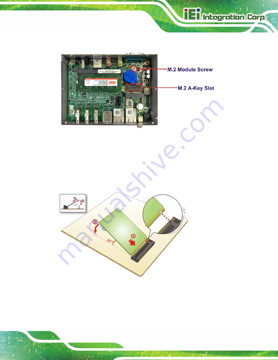
Locate the M.2 A-key slot on the motherboard
.
Figure 3-5: M.2 A-key Slot Location
Step 1:
Detach the RTC battery and remove the M.2 module retention screw from the
motherboard.
Step 2:
Line up the notch on the WLAN module with the notch on the slot. Slide the
WLAN module into the slot at an angle of about 20º (
).
Figure 3-6: Inserting the WLAN Module
Step 3:
Secure the WLAN module with the retention screw previously removed (
).
Summary of Contents for IDS-310-AL
Page 15: ...IDS 310 AL Embedded System Page 1 Chapter 1 1 Introduction...
Page 23: ...IDS 310 AL Embedded System Page 9 Chapter 2 2 Unpacking...
Page 26: ...IDS 310 AL Embedded System Page 12 Chapter 3 3 Installation...
Page 37: ...IDS 310 AL Embedded System Page 23 Figure 3 16 Hook Onto Mounting Bracket...
Page 47: ...IDS 310 AL Embedded System Page 33 Chapter 4 4 BIOS...
Page 81: ...IDS 310 AL Embedded System Page 67 Chapter 5 5 Maintenance...
Page 85: ...IDS 310 AL Embedded System Page 71 Chapter 6 6 Interface Connectors...
Page 93: ...IDS 310 AL Embedded System Page 79 Appendix A A Regulatory Compliance...
Page 98: ...IDS 310 AL Embedded System Page 84 Appendix B B Safety Precautions...
Page 104: ...IDS 310 AL Embedded System Page 90 Appendix C C BIOS Menu Options...
Page 107: ...IDS 310 AL Embedded System Page 93 Appendix D D Watchdog Timer...
Page 110: ...IDS 310 AL Embedded System Page 96 Appendix E E Error Beep Code...
Page 112: ...IDS 310 AL Embedded System Page 98 Appendix F F Hazardous Materials Disclosure...


