background image


ICE-BDE-T7 COM Express Module 

Page 88 

此附件旨在确保本产品符合中国

RoHS

标准。以下表格标示此产品中某有毒物质的含量符

合中国

RoHS

标准规定的限量要求。


本产品上会附有

环境友好使用期限

的标签,此期限是估算这些物质

不会有泄漏或突变

年限。本产品可能包含有较短的环境友好使用期限的可替换元件,像是电池或灯管,这些元

件将会单独标示出来。


部件名称


有毒有害物质或元素


(Pb) 


(Hg) 


(Cd) 

六价铬


(CR(VI)) 

多溴联苯


(PBB) 

多溴二苯


(PBDE) 

壳体


显示


印刷电路板


金属螺帽


电缆组装


风扇组装


电力供应组装


电池


O: 

表示该有毒有害物质在该部件所有物质材料中的含量均在

SJ/T 11363-2006 (

现由

GB/T 26572-2011

取代

标准规定的限量要求以下。


X: 

表示该有毒有害物质至少在该部件的某一均质材料中的含量超出

SJ/T 11363-2006 (

现由

GB/T 

26572-2011

取代

标准规定的限量要求。


Summary of Contents for ICE-BDE-T7

Page 1: ...ress Module Page i User Manual COM Express R3 0 Module Type 7 with Intel Xeon Processor D 1548 D 1518 D 1508 Two ECC DDR4 SO DIMM GbE 10G KR NCSI SATA 6Gb s PCIe Gen3 and RoHS MODEL ICE BDE T7 Rev 1 0...

Page 2: ...ICE BDE T7 COM Express Module Page ii Revision Date Version Changes February 2 2018 1 01 Added a new SKU ICE BDE T7 1508 December 13 2017 1 00 Initial release...

Page 3: ...ages arising out of the use or inability to use the product or documentation even if advised of the possibility of such damages This document contains proprietary information protected by copyright Al...

Page 4: ...nal injury Warnings should be taken seriously CAUTION Cautionary messages should be heeded to help reduce the chance of losing data or damaging the product NOTE These messages inform the reader of ess...

Page 5: ...CKING LIST 11 2 4 OPTIONAL ITEMS 12 3 CONNECTORS 13 3 1 PERIPHERAL INTERFACE CONNECTORS 14 3 1 1 ICE BDE T7 Layout 14 3 1 2 Peripheral Interface Connectors 15 3 2 INTERNAL PERIPHERAL CONNECTORS 15 3 2...

Page 6: ...on 43 5 3 3 iWDD Super IO Configuration 45 5 3 3 1 Serial Port n Configuration 46 5 3 4 RTC Wake Settings 48 5 3 5 Serial Port Console Redirection 49 5 3 5 1 Legacy Console Redirection Settings 50 5 3...

Page 7: ...SECURITY 66 5 7 BOOT 67 5 8 SAVE EXIT 69 6 SOFTWARE DRIVERS 71 6 1 SOFTWARE INSTALLATION 72 A REGULATORY COMPLIANCE 73 B PRODUCT DISPOSAL 75 C BIOS OPTIONS 77 D DIGITAL I O INTERFACE 80 E WATCHDOG TI...

Page 8: ...3 2 Connectors Solder Side 14 Figure 3 3 COM Express A B Connector Location 16 Figure 3 4 COM Express C D Connector Location 20 Figure 3 5 CPLD Programming Connector Location 24 Figure 3 6 SO DIMM Co...

Page 9: ...heral Interface Connectors 15 Table 3 2 COM Express A B Connector Pin Definitions 19 Table 3 3 COM Express C D Connector Pin Definitions 23 Table 3 4 CPLD Programming Connector Pin Definitions 24 Tabl...

Page 10: ...ngs 50 BIOS Menu 11 Console Redirection Settings 51 BIOS Menu 12 USB Configuration 53 BIOS Menu 13 IEI Feature 54 BIOS Menu 14 IntelRCSetup 55 BIOS Menu 15 Processor Configuration 56 BIOS Menu 16 IIO...

Page 11: ...ICE BDE T7 COM Express Module Page 1 Chapter 1 1 Introduction...

Page 12: ...T7 is preinstalled with Intel Xeon D 1548 D 1518 or D 1508 processor The COM Express standard allows the COM Express baseboard to be designed while leaving the choice of processor till the later stage...

Page 13: ...7 1508 Intel Xeon D 1508 2 2 GHz 2 3 MB 25 W Table 1 1 Model Variations 1 3 Features Some of the ICE BDE T7 COM Express module features are listed below Complies with COM Express Type 7 form factor On...

Page 14: ...ICE BDE T7 COM Express Module Page 4 1 4 Board Overview The on board components and connectors of the ICE BDE T7 are shown in the figures below Figure 1 2 On board Components and Connectors...

Page 15: ...OM Express Module Page 5 1 5 Dimensions The main dimensions of the ICE BDE T7 are shown in the diagrams below Figure 1 3 ICE BDE T7 Dimensions without heatsink mm Figure 1 4 ICE BDE T7 Dimensions with...

Page 16: ...ICE BDE T7 COM Express Module Page 6 1 6 Data Flow Figure 1 5 shows the data flow between the system chipset the CPU and other components installed on the motherboard Figure 1 5 Data Flow Diagram...

Page 17: ...l of 32 GB of memory Support ECC BIOS UEFI BIOS Watchdog Timer Software programmable supports 1 255 sec system reset Ethernet Intel I210 Ethernet controller 10G Sideband Signals 10G_INT 10G_PHY_MDC MD...

Page 18: ...e Page 8 ICE BDE T7 Operating Temperature 20 C 60 C with 0 7m s air flow Storage Temperature 30 C 70 C Operating Humidity 5 95 non condensing Dimensions 125 mm x 95 mm Weight GW NW 600 g 300 g Table 1...

Page 19: ...ICE BDE T7 COM Express Module Page 9 Chapter 2 2 Packing List...

Page 20: ...atic discharge Self grounding Touch a grounded conductor every few minutes to discharge any excess static buildup Use an anti static pad When configuring any circuit board place it on an anti static m...

Page 21: ...ion Contact the IEI reseller or vendor the ICE BDE T7 was purchased from or contact an IEI sales representative directly by sending an email to sales ieiworld com The ICE BDE T7 is shipped with the fo...

Page 22: ...s Module Page 12 2 4 Optional Items The following are optional components which may be separately purchased Item and Part Number Image Baseboard for COM Express Type 7 modules P N ICE DB T7 i2 R10 Tab...

Page 23: ...ICE BDE T7 COM Express Module Page 13 Chapter 3 3 Connectors...

Page 24: ...Peripheral Interface Connectors This chapter details all the connectors 3 1 1 ICE BDE T7 Layout The figures below show all the connectors on the front side and the solder side Figure 3 1 Connectors Fr...

Page 25: ...O DIMM slot 260 pin SO DIMM slot DIMM1 DIMM2 Debug port LPC 12 pin wafer DBG_PORT1 Debug port EC 20 pin FPC DBG_EC1 SPI flash connector BIOS 6 pin wafer J_SPI1 SPI flash connector EC 6 pin wafer J_EC1...

Page 26: ...I2 B6 LPC_AD2 A7 GBE0_MDI2 B7 LPC_AD3 A8 NC B8 LPC_DRQ 0 A9 GBE0_MDI1 B9 NC A10 GBE0_MDI1 B10 LPC_CLK A11 GND B11 GND A12 GBE0_MDI0 B12 PWRBTN A13 GBE0_MDI0 B13 SMB_CK A14 NC B14 SMB_DATA A15 PM_SLP_S...

Page 27: ...DP_5 B36 PE2_RX_DP_5 A37 PE2_TX_DN_ 5 B37 PE2_RX_DN_ 5 A38 GND B38 GND A39 PE2_TX_DP_4 B39 PE2_RX_DP_4 A40 PE2_TX_DN_ 4 B40 PE2_RX_DN_ 4 A41 GND B41 GND A42 USB2 B42 USB3 A43 USB2 B43 USB3 A44 USB_2_3...

Page 28: ...6 WAKE0 A67 DIN2 B67 NC A68 PCIE_TX_DP_1 B68 PCIE_RX_DP_1 A69 PCIE_TX_DN _1 B69 PCIE_RX_DN _1 A70 GND B70 GND A71 PE2_TX_DP_0 B71 PE2_RX_DP_0 A72 PE2_TX_DN_ 0 B72 PE2_RX_DN_ 0 A73 GND B73 GND A74 PE2_...

Page 29: ...D B100 GND A101 RS2_TX B101 FAN_PWMOUT A102 RS2_RX B102 FAN_TACHIN A103 LID B103 SLEEP A104 VCC_12V B104 VCC_12V A105 VCC_12V B105 VCC_12V A106 VCC_12V B106 VCC_12V A107 VCC_12V B107 VCC_12V A108 VCC_...

Page 30: ...TXN_1 C7 USB3_RXP_1 D7 USB3_TXP_1 C8 GND D8 GND C9 USB3_RXN_2 D9 USB3_TXN_2 C10 USB3_RXP_2 D10 USB3_TXP_2 C11 GND D11 GND C12 USB3_RXN_3 D12 USB3_TXN_3 C13 USB3_RXP_3 D13 USB3_TXP_3 C14 GND D14 GND C1...

Page 31: ...SH_CLK C39 LAN_MDIO1_LED1_0 D39 LAN_FLSH_DO C40 LAN_SDP0_1 D40 LAN_SDP0_0 C41 GND D41 GND C42 GBE_KR_RX1_P D42 GBE_KR_TX1_P C43 GBE_KR_RX1_N D43 GBE_KR_TX1_N C44 GND D44 GND C45 LAN_MDC0_LED0_1 D45 LA...

Page 32: ..._5 C69 PE1_RX_DN _5 D69 PE1_TX_DN _5 C70 GND D70 GND C71 PE1_RX_DP_6 D71 PE1_TX_DP_6 C72 PE1_RX_DN _6 D72 PE1_TX_DN _6 C73 GND D73 GND C74 PE1_RX_DP_7 D74 PE1_TX_DP_7 C75 PE1_RX_DN _7 D75 PE1_TX_DN _7...

Page 33: ...N _13 C96 GND D96 GND C97 NC D97 NC C98 PE1_RX_DP_14 D98 PE1_TX_DP_14 C99 PE1_RX_DN _14 D99 PE1_TX_DN _14 C100 GND D100 GND C101 PE1_RX_DP_15 D101 PE1_TX_DP_15 C102 PE1_RX_DN _15 D102 PE1_TX_DN _15 C1...

Page 34: ...4 mm CN Location See Figure 3 5 CN Pinouts See Table 3 4 The CPLD programming connector location and pinouts are shown below Figure 3 5 CPLD Programming Connector Location Pin No Description 1 VCC3 3S...

Page 35: ...6 The SO DIMM connectors are for installing DDR4 memory on the system NOTE For dual channel configuration always install two identical memory modules that feature the same capacity timings voltage nu...

Page 36: ...cation See Figure 3 7 CN Pinouts See Table 3 5 The LPC debug port location and pinouts are shown below Figure 3 7 LPC Debug Port Location Pin No Description 1 NC 2 LPC_CLK_REF 3 SYS_RESET 4 LPC_FRAME...

Page 37: ...outs See Table 3 6 The EC debug port location and pinouts are shown below Figure 3 8 EC Debug Port Location Pin No Description Pin No Description 1 KSI0 11 KSO9 2 KSO0 12 KSO10 3 KSO1 13 KSO12 4 KSO2...

Page 38: ...pin wafer p 1 25 mm CN Location See Figure 3 9 CN Pinouts See Table 3 7 The BIOS SPI flash connector location and pinouts are shown below Figure 3 9 BIOS SPI Flash Connector Location Pin No Descripti...

Page 39: ...pin wafer p 1 25 mm CN Location See Figure 3 10 CN Pinouts See Table 3 8 The EC SPI flash connector location and pinouts are shown below Figure 3 10 EC SPI Flash Connector Location Pin No Description...

Page 40: ...ICE BDE T7 COM Express Module Page 30 Chapter 4 4 Installation...

Page 41: ...stband can help to prevent ESD from damaging the board Self grounding Before handling the board touch any grounded conducting material During the time the board is handled frequently touch any conduct...

Page 42: ...rom the body and helps prevent ESD damage Place the ICE BDE T7 on an antistatic pad o When installing or configuring the motherboard place it on an antistatic pad This helps to prevent potential ESD d...

Page 43: ...dentical memory modules that feature the same capacity timings voltage number of ranks and the same brand To install a SO DIMM into a SO DIMM socket please follow the steps below and refer to Figure 4...

Page 44: ...e thermal pad acts as a thermal interface between the module and the heatsink The heatsink must be installed on the ICE BDE T7 to maintain proper operating temperatures Make sure to maintain the heats...

Page 45: ...Ensure a thermal pad is placed on the CPU of the ICE BDE T7 Step 3 Place the heatsink on the ICE BDE T7 aligning the retention screw holes Figure 4 3 Step 4 Secure the heatsink to the ICE BDE T7 and...

Page 46: ...ICE BDE T7 COM Express Module Page 36 Chapter 5 5 BIOS...

Page 47: ...Press the DELETE or F2 key as soon as the system is turned on or 2 Press the DELETE or F2 key when the Press Del to enter SETUP message appears on the screen 0 If the message disappears before the DE...

Page 48: ...ons for the highlighted item appears To exit the Help Window press ESC or the F1 key again 5 1 4 Unable to Reboot after Configuration Changes If the computer cannot boot after changes to the system co...

Page 49: ...6384 MB System Date Fri 01 01 2010 System Time 00 18 35 Set the Date Use Tab to switch between Data elements Select Screen Select Item EnterSelect Change Opt F1 General Help F2 Previous Values F3 Opti...

Page 50: ...l Port Console Redirection USB Configuration iEi Feature Select AC power state when power is re applied after a power failure Select Screen Select Item EnterSelect Change Opt F1 General Help F2 Previo...

Page 51: ...ty Device Found Enables or Disables BIOS support for security device O S will not show Security Device TCG EFI protocol and INT1A interface will not be available Select Screen Select Item EnterSelect...

Page 52: ...1 791 V 5V 5 023 V 12V 11 806 V DDR 1 208 V 3 3V 3 253 V 3 3VSB 3 277 V Smart Fan Mode Configuration Smart Fan Mode Select Select Screen Select Item EnterSelect Change Opt F1 General Help F2 Previous...

Page 53: ...de fan slope PWM 2 Smart Fan Mode Select Select Screen Select Item EnterSelect Change Opt F1 General Help F2 Previous Values F3 Optimized Defaults F4 Save Exit ESC Exit Version 2 18 1260 Copyright C 2...

Page 54: ...perature 30 WARNING Setting this value too high may cause the fan to speed up only when the CPU is at a very high temperature and therefore cause the system to be damaged The Auto mode fan off tempera...

Page 55: ...al number between 1 and 8 5 3 3 iWDD Super IO Configuration Use the iWDD Super IO Configuration menu BIOS Menu 6 to set or change the configurations for the serial ports Aptio Setup Utility Copyright...

Page 56: ...ues F3 Optimized Defaults F4 Save ESC Exit Version 2 18 1260 Copyright C 2017 American Megatrends Inc BIOS Menu 7 Serial Port n Configuration 5 3 3 1 1 Serial Port 1 Configuration Serial Port Enabled...

Page 57: ...e Serial Port option to enable or disable the serial port Disabled Disable the serial port Enabled DEFAULT Enable the serial port Change Settings Auto Use the Change Settings option to change the seri...

Page 58: ...ate hr min sec specified Select Screen Select Item EnterSelect F1 General Help F2 Previous Values F3 Optimized Defaults F4 Save ESC Exit Version 2 18 1260 Copyright C 2017 American Megatrends Inc BIOS...

Page 59: ...remotely by re directing keyboard input and text output through the serial port Aptio Setup Utility Copyright C 2017 American Megatrends Inc Advanced COM1 Console Redirection Disabled Console Redirec...

Page 60: ...figured Aptio Setup Utility Copyright C 2016 American Megatrends Inc Advanced Legacy Serial Redirection Port COM1 Select a COM port to display redirection of Legacy OS and Legacy OPROM Messages Select...

Page 61: ...NSI Extended ASCII char set VT100 ASCII char set VT100 Extends VT100 to support color function keys etc VT UTF8 Uses UTF8 encoding to map Unicode chars onto 1 or more bytes Select Screen Select Item E...

Page 62: ...e serial port transmission speed at 115200 Data Bits 8 Use the Data Bits option to specify the number of data bits 7 Sets the data bits at 7 8 DEFAULT Sets the data bits at 8 Parity None Use the Parit...

Page 63: ...Aptio Setup Utility Copyright C 2017 American Megatrends Inc Advanced USB Configuration USB Controllers 1 EHCI 1 XHCI USB Devices 1 Keyboard 2 Hubs Legacy USB Support Enabled Enables Legacy USB suppo...

Page 64: ...Legacy USB support enabled Disabled Legacy USB support disabled Auto Legacy USB support disabled if no USB devices are connected 5 3 7 IEI Feature Use the IEI Feature menu BIOS Menu 13 to configure O...

Page 65: ...Menu 14 to configure the system processor and chipset Aptio Setup Utility Copyright C 2017 American Megatrends Inc Main Advanced IntelRCSetup Server Mgmt Security Boot Event Logs Save Exit Processor...

Page 66: ...RAM 6144KB Processor 0 Version Intel R Xeon R D 1518 2 20GHz Hyper Threading Enable Intel TXT Disable VMX Disable EIST Enable CPU C state Disable Enable Hyper Threading Software Method to Enable Disab...

Page 67: ...ombined with third party software Intel Virtualization technology allows several OSs to run on the same system at the same time Disable DEFAULT Disables Intel Virtualization Technology Enable Enables...

Page 68: ...Optimized Defaults F4 Save Exit ESC Exit Version 2 18 1260 Copyright C 2017 American Megatrends Inc BIOS Menu 16 IIO Configuration 5 4 2 1 IIO0 Configuration Use the IIO0 Configuration submenu BIOS Me...

Page 69: ...ure the VT d settings Aptio Setup Utility Copyright C 2017 American Megatrends Inc IntelRCSetup Intel VT for Directed I O VT d Intel VT for Directed I O VT d Disable Enable Disable Intel Virtualizatio...

Page 70: ...io Setup Utility Copyright C 2017 American Megatrends Inc IntelRCSetup IIO South Complex Configuration Disable SC GbE Disable Disables South Complex GbE completely Select Screen Select Item EnterSelec...

Page 71: ...timized Defaults F4 Save Exit ESC Exit Version 2 18 1260 Copyright C 2017 American Megatrends Inc BIOS Menu 20 PCH Configuration 5 4 3 1 PCI Express Configuration Use the PCI Express Configuration sub...

Page 72: ...rican Megatrends Inc IntelRCsetup PCH SATA Configuration STAT Controller Enabled Configure SATA as AHCI SATA1 Not Installed Hot Plug Disabled SATA2 Not Installed Hot Plug Disabled Enable or Disable SA...

Page 73: ...r RAID devices IDE Configures SATA devices as IDE device AHCI DEFAULT Configures SATA devices as AHCI device RAID Configures SATA devices as RAID device Hot Plug Disabled Use the Hot Plug option to en...

Page 74: ...Event Logs Save Exit BMC Self Test Status FAILED BMC Firmware Revision Unknown System Event Log Press Enter to change the SEL event log configuration Select Screen Select Item EnterSelect Change Opt F...

Page 75: ...er Select Change Opt F1 General Help F2 Previous Values F3 Optimized Defaults F4 Save Exit ESC Exit Version 2 18 1260 Copyright C 2017 American Megatrends Inc BIOS Menu 24 System Event Log SEL Compone...

Page 76: ...its access to Setup and is only asked for when entering Setup If ONLY the User s password is set then this is a power on password and must be entered to boot or enter Setup In Setup the User will have...

Page 77: ...keyboard NumLock state Select Screen Select Item EnterSelect Change Opt F1 General Help F2 Previous Values F3 Optimized Defaults F4 Save Exit ESC Exit Version 2 18 1260 Copyright C 2017 American Mega...

Page 78: ...T messages displayed Enabled DEFAULT OEM Logo displayed instead of POST messages UEFI Boot Disabled Use the UEFI Boot option to enable or disable to boot from the UEFI devices Enabled Boot from UEFI d...

Page 79: ...ity Copyright C 2017 American Megatrends Inc Main Advanced IntelRCSetup Server Mgmt Security Boot Event Logs Save Exit Save Changes and Reset Discard Changes and Reset Restore Defaults Save as User De...

Page 80: ...ram Restore Defaults Use the Restore Defaults option to load the optimal default values for each of the parameters on the Setup menus F3 key can be used for this operation Save as User Defaults Use th...

Page 81: ...ICE BDE T7 COM Express Module Page 71 6 Software Drivers Chapter 6...

Page 82: ...the drivers for the ICE BDE T7 are on the CD that came with the system To install the drivers please follow the steps below Step 1 Insert the CD that came with the system into a CD drive connected to...

Page 83: ...ICE BDE T7 COM Express Module Page 73 Appendix A A Regulatory Compliance...

Page 84: ...nterference that may cause undesired operation This equipment has been tested and found to comply with the limits for a Class A digital device pursuant to part 15 of the FCC Rules These limits are des...

Page 85: ...ICE BDE T7 COM Express Module Page 75 B Product Disposal Appendix B...

Page 86: ...classified as electronic device in terms of the European Directive 2012 19 EU WEEE and must not be disposed of as domestic garbage EU wide legislation as implemented in each Member State requires that...

Page 87: ...ICE BDE T7 COM Express Module Page 77 Appendix C C BIOS Options...

Page 88: ...ode fan slope PWM 2 45 Serial Port Enabled 46 Change Settings Auto 46 Serial Port Enabled 47 Change Settings Auto 47 Wake system with Fixed Time Disabled 48 Console Redirection Disabled 50 Legacy Seri...

Page 89: ...L No 65 When SEL is full Do Nothing 66 Administrator Password 66 User Password 66 Bootup NumLock State On 67 Quiet Boot Enabled 68 UEFI Boot Disabled 68 Launch PXE OpROM Disabled 68 Option ROM Message...

Page 90: ...ICE BDE T7 COM Express Module Page 80 Appendix D D Digital I O Interface...

Page 91: ...rol the on off circuit of external devices or TTL devices Data can be read or written to the selected address to enable the DIO functions NOTE For further information please refer to the datasheet for...

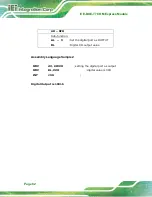
Page 92: ...Page 82 AH 6FH Sub function AL 9 Set the digital port as OUTPUT BL Digital I O output value Assembly Language Sample 2 MOV AX 6F09H setting the digital port as output MOV BL 09H digital value is 09H I...

Page 93: ...ICE BDE T7 COM Express Module Page 83 Appendix E E Watchdog Timer...

Page 94: ...INT 15H is used to control the Watchdog Timer INT 15H AH 6FH Sub function AL 2 Sets the Watchdog Timer s period BL Time out value Its unit second is dependent on the item Watchdog Timer unit select i...

Page 95: ...he system resets EXAMPLE PROGRAM INITIAL TIMER PERIOD COUNTER W_LOOP MOV AX 6F02H setting the time out value MOV BL 30 time out value is 48 seconds INT 15H ADD THE APPLICATION PROGRAM HERE CMP EXIT_AP...

Page 96: ...ICE BDE T7 COM Express Module Page 86 Appendix F F Hazardous Materials Disclosure...

Page 97: ...lamps These components will be separately marked Please refer to the following table Part Name Toxic or Hazardous Substances and Elements Lead Pb Mercury Hg Cadmium Cd Hexavalent Chromium CR VI Polyb...

Page 98: ...ress Module Page 88 RoHS RoHS Pb Hg Cd CR VI PBB PBDE O O O O O O O O O O O O O O O O O O O O O O O O O O O O O O O O O O O O O O O O O O O O O O O O O SJ T 11363 2006 GB T 26572 2011 X SJ T 11363 200...

Reviews:

Related manuals for ICE-BDE-T7