E-265-910/EP-267-910 Enrich POS System
Page 46
Step 3:
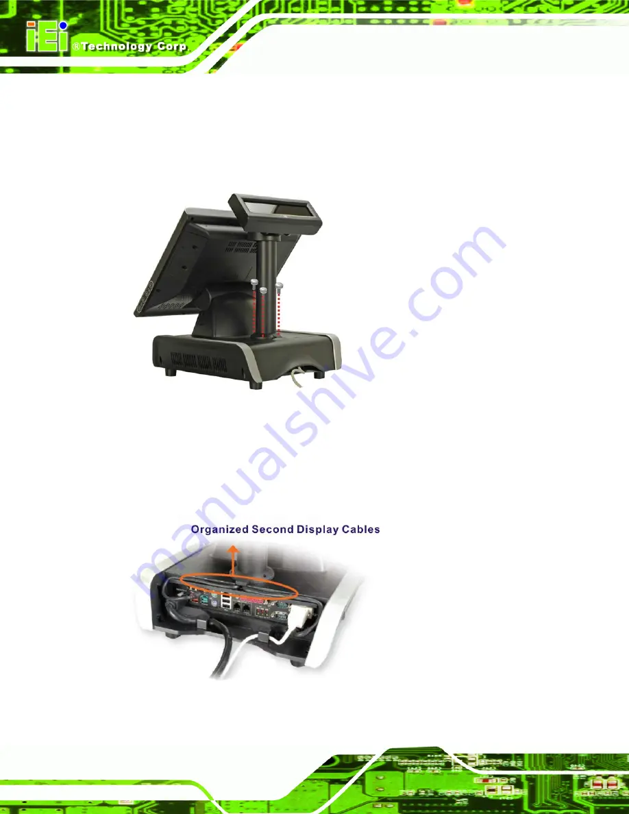
Align the thee retention screw holes on the second display device with the
retention screw holes on the mounting hole. Insert the three retention screws to
secure the second display to the EP-265-910/EP-267-910(
).
Figure 4-16: Second Display Installation
Step 4:
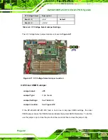
Organize the second display cables and connect the connector to the
connectors on the I/O interface panel (Figure 4-17).
Figure 4-17: Organized Second Display Cables
Summary of Contents for EP-265-910
Page 1: ...EP 265 910 EP 267 910 Enrich POS System Page i EP 265 910 EP 267 910 Enrich POS System ...
Page 15: ...EP 265 910 EP 267 910 Enrich POS System Page 1 1 Introduction Chapter 1 ...
Page 26: ...E 265 910 EP 267 910 Enrich POS System Page 12 2 Detailed Specifications Chapter 2 ...
Page 41: ...EP 265 910 EP 267 910 Enrich POS System Page 27 3 Unpacking Chapter 3 ...
Page 44: ...E 265 910 EP 267 910 Enrich POS System Page 30 4 Installation Chapter 4 ...
Page 66: ...E 265 910 EP 267 910 Enrich POS System Page 52 5 System Maintenance Chapter 4 ...
Page 72: ...E 265 910 EP 267 910 Enrich POS System Page 58 6 AMI BIOS Setup Chapter 6 ...
Page 116: ...E 265 910 EP 267 910 Enrich POS System Page 102 7 System Monitoring Chapter 7 ...
Page 119: ...EP 265 910 EP 267 910 Enrich POS System Page 105 A System Specifications Appendix A ...
Page 125: ...EP 265 910 EP 267 910 Enrich POS System Page 111 B External Connector Pinouts Appendix B ...
Page 128: ...E 265 910 EP 267 910 Enrich POS System Page 114 C Safety Precautions Appendix C ...
Page 132: ...E 265 910 EP 267 910 Enrich POS System Page 118 D BIOS Configuration Options Appendix D ...
Page 136: ...E 265 910 EP 267 910 Enrich POS System Page 122 E Watchdog Timer Appendix E ...
Page 139: ...EP 265 910 EP 267 910 Enrich POS System Page 125 F Hazardous Materials Disclosure Appendix F ...
Page 143: ...EP 265 910 EP 267 910 Enrich POS System Page 129 G Index ...


