background image


DRPC-120-BTi Embedded System 

Page 17 


Access can only be gained by SERVICE PERSONS or by USERS who have 

been instructed about the reasons for the restrictions applied to the location 

and about any precautions that shall be taken. 


Access is through the use of a TOOL or lock and key, or other means of 

security, and is controlled by the authority responsible for the location. 

3.2 Internal Access Panel Removal 

Before installing or maintaining the internal components, the internal access panel must 

be removed from the DRPC-120-BTi. Follow the steps below to complete the task. 

Step 1: 

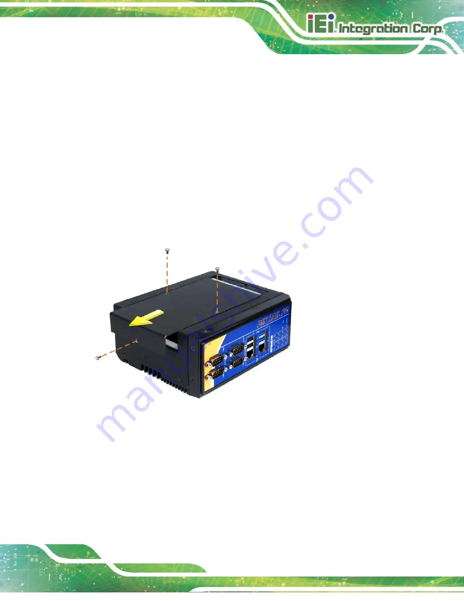
Remove the three retention screws indicated i

Figure 3-1

. 

Step 2: 

Slide the panel and gently lift the panel (

Figure 3-1

).   


Figure 3-1: Internal Access Panel Removal 

Summary of Contents for DRPC-120-BTi

Page 1: ...System Page i User Manual MODEL DRPC 120 BTi Fanless Embedded System with Intel Atom E3845 CPU DIN Rail Mounting Support LED Indicators Dual GbE USB DIO Serial Ports 9V 28V DC Power Input RoHS Compliant Rev 1 10 July 19 2021 ...

Page 2: ... Checklist Updated Section 3 11 Available Drivers March 1 2017 1 04 Modified Chapter 2 July 30 2015 1 03 Added the Watchdog Timer appendix June 11 2015 1 02 Added maximum input wattage 36 W information March 25 2015 1 01 Added a warning message in Section 3 3 HDD Installation Added Appendix A Regulatory Compliance November 20 2014 1 00 Initial release ...

Page 3: ...mages arising out of the use or inability to use the product or documentation even if advised of the possibility of such damages This document contains proprietary information protected by copyright All rights are reserved No part of this manual may be reproduced by any mechanical electronic or other means in any form without prior written permission of the manufacturer TRADEMARKS All registered t...

Page 4: ...AUTION Cautionary messages should be heeded to help reduce the chance of losing data or damaging the product NOTE These messages inform the reader of essential but non critical information These messages should be read carefully as any directions or instructions contained therein can help avoid making mistakes HOT SURFACE This symbol indicates a hot surface that should not be touched without takin...

Page 5: ...ON PRECAUTIONS 16 3 1 1 High Surface Temperature 16 3 2 INTERNAL ACCESS PANEL REMOVAL 17 3 3 HDD INSTALLATION 18 3 4 MSATA SSD INSTALLATION 19 3 5 IPMI MODULE INSTALLATION OPTIONAL 21 3 6 CLEAR CMOS 22 3 7 AT ATX MODE SELECTION 23 3 8 MOUNTING THE SYSTEM 23 3 9 EXTERNAL PERIPHERAL INTERFACE CONNECTORS 25 3 9 1 Digital Input Output Terminal Block 26 3 9 2 LAN Connectors 27 3 9 3 Power Input 3 pin T...

Page 6: ...e to Reboot after Configuration Changes 43 5 1 5 BIOS Menu Bar 43 5 2 MAIN 44 5 3 ADVANCED 46 5 3 1 ACPI Settings 47 5 3 2 Super IO Configuration 48 5 3 2 1 Serial Port n Configuration 49 5 3 2 1 1 Serial Port 1 Configuration 49 5 3 2 1 2 Serial Port 2 Configuration 50 5 3 2 1 3 Serial Port 3 Configuration 51 5 3 2 1 4 Serial Port 4 Configuration 53 5 3 3 iWDD H W Monitor 54 5 3 3 1 Smart Fan Mode...

Page 7: ...lot Half Size MINI PCIE1 80 6 2 9 SATA 3Gb s Connector SATA1 81 6 2 10 SATA Power Connector SATA_PWR1 82 6 2 11 SPI Flash Connector JSPI1 82 6 2 12 SPI Flash Connector EC JSPI2 82 6 2 13 USB Connector USB1 83 6 3 EXTERNAL INTERFACE PANEL CONNECTORS 83 6 3 1 Digital I O Terminal Block J1 84 6 3 2 Power Input Terminal Block DC_IN1 84 6 3 3 RJ 45 LAN Connector LAN1 84 6 3 4 RJ 45 LAN Connector LAN2 8...

Page 8: ...ols 95 B 1 4 Product Disposal 96 B 2 MAINTENANCE AND CLEANING PRECAUTIONS 96 B 2 1 Maintenance and Cleaning 96 B 2 2 Cleaning Tools 97 C DIGITAL I O INTERFACE 98 D WATCHDOG TIMER 101 E HAZARDOUS MATERIALS DISCLOSURE 104 E 1 ROHS II DIRECTIVE 2015 863 EU 105 E 2 CHINA ROHS 106 ...

Page 9: ...23 Figure 3 9 AT ATX Switch Location 23 Figure 3 10 DIN Rail Mounting Bracket Installation 24 Figure 3 11 Attach the Mounting Bracket to the DIN Rail 24 Figure 3 12 Mounting the System 25 Figure 3 13 DIO Terminal Block Pinout Location 26 Figure 3 14 RJ 45 Ethernet Connector 27 Figure 3 15 3 pin Power Terminal Block Pinout Location 28 Figure 3 16 RS 232 Serial Port Pinout Location 29 Figure 3 17 RS...

Page 10: ... 6 2 Audio Line out Connector LINE_OUT1 Pinouts 78 Table 6 3 Audio Mic in Connector MIC_IN1 Pinouts 78 Table 6 4 Battery Connector BAT1 Pinouts 78 Table 6 5 Chassis Intrusion Connector CHASSIE1 Pinouts 78 Table 6 6 CPU Fan Connector CPU_FAN1 Pinouts 79 Table 6 7 LED Signal Connector OLED1 Pinouts 79 Table 6 8 PCIe Mini Card Slot Full Size M_PCIE1 Pinouts 80 Table 6 9 PCIe Mini Card Slot Half Size ...

Page 11: ...6 19 RJ 45 LAN Connector LAN2 Pinouts 85 Table 6 20 RS 232 Serial Port COM1 2 Pinouts 85 Table 6 21 RS 422 485 Serial Port COM3 4 Pinouts 85 Table 6 22 USB 2 0 Connectors USB2 Pinouts 86 Table 6 23 USB 3 2 Gen1 Connectors USB1 Pinouts 86 Table 6 24 VGA Connector VGA1 Pinouts 87 DRPC 120 BTi ...

Page 12: ......

Page 13: ...DRPC 120 BTi Embedded System Page 1 Chapter 1 1 Introduction ...

Page 14: ... Atom E3845 processor It is designed for harsh environment applications and supports DIN rail mounting method The DRPC 120 BTi accepts a wide range of DC power input 9 V 28 V allowing it to be powered anywhere Two USB 3 2 Gen1 5Gb s two USB 2 0 two GbE two RS 232 two RS 422 485 and one 8 bit DIO provide rich I O options for various applications ...

Page 15: ...ed one 2 GB DDR3L SO DIMM system max 8 GB Supports one mSATA and one 2 5 SATA HDD Wide range DC power input 9 V 28 V max 36 W Extended temperature fanless design supports 20 C 60 C with SSD Two PCIe Mini card slots Serial interfaces with isolation protection 8 bit digital IO 4 bit output 4 bit input Supports two GbE two USB 3 2 Gen1 5Gb s two USB 2 0 two RS 232 and two RS 422 485 LED indicators Ro...

Page 16: ...tains 2 x RJ 45 Gigabit LAN ports 2 x RS 232 serial ports with isolation 2 x RS 422 485 serial ports with isolation 2 x USB 3 2 Gen1 5Gb s ports 2 x USB 2 0 ports LED indicators The overview of the front panels of both model are shown in Figure 1 2 and Error Reference source not found Figure 1 2 Front Panel ...

Page 17: ...x 8 bit digital I O Phoenix terminal block 4 bit input 4 bit output 1 x 9 V 28 V DC power terminal block 1 x AT ATX power switch 1 x HDMI connector 1 x Power button 1 x Reset button 1 x VGA connector An overview of the top panel is shown in Figure 1 3 below Figure 1 3 DRPC 120 BTi Top Panel ...

Page 18: ...HDD Green Blinking Storage device accessing Off Storage device not accessing COM TX 1 4 Yellow On COM port is transmitting data Off COM port is not transmitting data COM RX 1 4 Green On COM port is receiving data Off COM port is not receiving data DIO DI 1 4 Yellow On Active Off Inactive DIO DO 1 4 Green On Active Off Inactive When the DIO is set to pull high the DIO LED indicators always light up...

Page 19: ...icrosoft Windows Embedded Standard 7 Storage HDD One 2 5 SATA 3Gb s HDD SSD bay mSATA One PCIe Mini full size card slot for mSATA module SATA 3Gb s I O and Indicators Ethernet 2 x RJ 45 ports RS 232 2 x DB 9 serial ports with 3KV isolation protection RS 422 RS 485 2 x DB 9 serial ports with 3KV isolation protection USB 2 x USB 3 2 Gen1 5Gb s ports 2 x USB 2 0 ports Display Supports resolution up t...

Page 20: ... Mechanical Mounting DIN rail desktop Operating Temperature 20 C 60 C with air flow with SSD Storage Temperature 30 C 70 C Humidity 5 95 non condensing Chassis Construction Extruded aluminum alloy for fanless support Color Blue C Black C Operating Shock Half sine shock test 5G 11ms 3 shocks per axis Operating Vibration MIL STD 810F 514 5 C 2 SSD Safety CE FCC Weight Net Gross 1 4 kg 2 5 kg Physica...

Page 21: ...DRPC 120 BTi Embedded System Page 9 1 6 Dimensions The physical dimensions are shown below Figure 1 5 Physical Dimensions millimeters ...

Page 22: ...DRPC 120 BTi Embedded System Page 10 Chapter 2 2 Unpacking ...

Page 23: ...ic wristband Wearing a simple anti static wristband can help to prevent ESD from damaging the board Self grounding Before handling the board touch any grounded conducting material During the time the board is handled frequently touch any conducting materials that are connected to the ground Use an anti static pad When configuring the DRPC 120 BTi place it on an anti static pad This reduces the pos...

Page 24: ...or you purchased the DRPC 120 BTi from or contact an IEI sales representative directly To contact an IEI sales representative please send an email to sales ieiworld com The DRPC 120 BTi is shipped with the following components Quantity Item and Part Number Image Standard 1 DRPC 120 BTi 1 3 pin terminal block 2 5 pin terminal block 1 SATA cable P N 32801 000702 100 RS 1 SATA power cable P N 32102 0...

Page 25: ...or securing an PCIe Mini card The following table lists the optional items that can be purchased separately Optional Power adapter P N 63040 010036 121 RS Power cord European standard 1800 mm P N 32702 000400 200 RS Power cord American standard 1830 mm P N 32000 000025 RS Power cable DC jack 5 5x2 5 to 3 pin terminal block 200 mm P N 32102 026500 100 RS Wireless kit P N EMB WIFI KIT01 R11 ...

Page 26: ...DRPC 120 BTi Embedded System Page 14 Optional DIN Rail mounting kit P N DK DRPC R10 Flash disk mSATA 2GB 32GB 0 C 70 C P N IPE 5200IM xxx Flash disk mSATA 2GB 32GB 40 C 85 C P N IPE 5200VM xxx ...

Page 27: ...DRPC 120 BTi Embedded System Page 15 Chapter 3 3 Installation ...

Page 28: ...ion Make sure there is sufficient air circulation when installing the DRPC 120 BTi The DRPC 120 BTi s cooling vents must not be obstructed by any objects Blocking the vents can cause overheating of the DRPC 120 BTi Leave at least 5 cm of clearance around the DRPC 120 BTi to prevent overheating Grounding The DRPC 120 BTi should be properly grounded The voltage feeds must not be overloaded Adjust th...

Page 29: ...lock and key or other means of security and is controlled by the authority responsible for the location 3 2 Internal Access Panel Removal Before installing or maintaining the internal components the internal access panel must be removed from the DRPC 120 BTi Follow the steps below to complete the task Step 1 Remove the three retention screws indicated in Figure 3 1 Step 2 Slide the panel and gentl...

Page 30: ...cess panel from the DRPC 120 BTi Please follow the instruction described in Section 3 2 Step 2 Install the HDD into the bracket on the internal access panel and secure the HDD with four retention screws Figure 3 2 Step 3 Connect the SATA cable and the SATA power cable to the rear of the HDD Figure 3 2 Step 4 Connect the SATA cable and the SATA power cable from the HDD to the SATA connector and SAT...

Page 31: ...ions below Step 1 Remove the internal access panel from the DRPC 120 BTi Please follow the instruction described in Section 3 2 Step 2 Locate the PCIe Mini slot on the motherboard Figure 3 3 Figure 3 3 PCIe Mini Slot Location Step 3 Insert into the socket at an angle Line up the notch on the card with the notch on the connector Slide the PCIe Mini card into the socket at an angle of about 20º Figu...

Page 32: ...ing the PCIe Mini Card into the Socket Step 4 Secure the PCIe Mini card Secure the PCIe Mini card with the supplied retention screws Figure 3 5 Figure 3 5 Securing the PCIe Mini Card Step 5 Replace and secure the internal access panel to the system Step 0 ...

Page 33: ...all the iRIS 2400 module and refer to Section 3 10 for the setup procedure Step 1 Remove the internal access panel from the DRPC 120 BTi Please follow the instruction described in Section 3 2 Step 2 Locate the IPMI module slot on the motherboard Figure 3 3 Figure 3 6 IPMI Module Slot Location Step 3 Align the iRIS 2400 module with the IPMI module slot Align the notch on the module with the notch o...

Page 34: ...ar CMOS button clears the CMOS data and resets the system BIOS information To do this push the clear CMOS button for a few seconds If the CMOS Settings Wrong message is displayed during the boot up process the fault may be corrected by pressing the F1 to enter the CMOS Setup menu Do one of the following Enter the correct CMOS setting Load Optimal Defaults Load Failsafe Defaults After having done o...

Page 35: ...T ATX switch on the top panel as shown below Figure 3 9 Figure 3 9 AT ATX Switch Location 3 8 Mounting the System The DRPC 120 BTi embedded system can be mounted onto a DIN rail Follow the steps below to complete the task Step 1 Attach the supplied DIN rail mounting bracket to the rear panel of the embedded system Secure the bracket to the embedded system with three retention screws Figure 3 10 ...

Page 36: ...ting Bracket Installation NOTE In the diagrams below the DIN rail is already installed on a surface or on a chassis Step 2 Attach the upper edge of the mounting bracket to the DIN rail as shown in Figure 3 11 Figure 3 11 Attach the Mounting Bracket to the DIN Rail ...

Page 37: ...cket clips into place firmly Figure 3 12 Figure 3 12 Mounting the System 3 9 External Peripheral Interface Connectors The DRPC 120 BTi has the following connectors Detailed descriptions of the connectors can be found in the subsections below 8 bit DIO Ethernet Power input RS 232 RS 422 485 USB VGA HDMI ...

Page 38: ... block provides programmable input and output for external devices The digital I O provides 4 bit output and 4 bit input The pinouts for the digital I O terminal block are listed in the table below Pin Description Pin Description 1 DGI_0 2 DGO_0 3 DGI_1 4 DGO_1 5 DGI_2 6 DGO_2 7 DGI_3 8 DGO_3 9 Isolator GND 10 Isolator Vin Table 3 1 DIO Terminal Block Pinouts Figure 3 13 DIO Terminal Block Pinout ...

Page 39: ...ection to an external network Pin Description Pin Description 20 LAN1_MDI0P 24 LAN1_MDI2P 21 LAN1_MDI0N 25 LAN1_MDI2N 22 LAN1_MDI1P 26 LAN1_MDI3P 23 LAN1_MDI1N 27 LAN1_MDI3N Table 3 2 LAN1 Pinouts Pin Description Pin Description P2 TRD2P0 P6 TRD2P2 P3 TRD2N0 P7 TRD2N2 P4 TRD2P1 P8 TRD2P3 P5 TRD2N1 P9 TRD2N3 Table 3 3 LAN2 Pinouts Figure 3 14 RJ 45 Ethernet Connector ...

Page 40: ...king TX RX activity Orange 1 Gbps connection Table 3 4 RJ 45 Ethernet Connector LEDs 3 9 3 Power Input 3 pin Terminal Block CN Type 3 pin terminal block CN Location See Figure 1 3 CN Pinouts See Table 3 5 and Figure 3 15 Connect the leads of a 9 V 28 V DC power supply max 36 W into the terminal block Make sure that the power and ground wires are attached to the correct sockets of the connector Pin...

Page 41: ...nectors CN Location See Figure 1 2 CN Pinouts See Table 3 6 and Figure 3 16 RS 232 serial port devices can be attached to the DB 9 ports on the front panel Pin Description Pin Description 1 DCD 6 DSR 2 RXD 7 RTS 3 TXD 8 CTS 4 DTR 9 RI 5 GND Table 3 6 RS 232 Serial Port Pinouts Figure 3 16 RS 232 Serial Port Pinout Location ...

Page 42: ...CN Location See Figure 1 2 CN Pinouts See Table 3 7 and Figure 3 17 RS 422 485 serial port devices can be attached to the DB 9 ports on the front panel Pin RS 422 RS 485 1 RS 422TX RS 485D 2 RS 422TX RS 485D 3 RS 422RX 4 RS 422RX 5 GND 6 7 8 9 Table 3 7 RS 422 485 Serial Port Pinouts Figure 3 17 RS 422 485 Serial Port Pinout Locations ...

Page 43: ... USB 3 2 Gen1 connector pinouts are listed below Pin Description Pin Description 1 VCC 5 VCC 2 DATA 6 DATA 3 DATA 7 DATA 4 GROUND 8 GROUND Table 3 8 USB 2 0 Port USB3 USB4 Pinouts Pin Description Pin Description 1 VCC 10 VCC 2 USB_DATA 11 USB_DATA 3 USB_DATA 12 USB_ DATA 4 GND 13 GND 5 USB3_RX 14 USB3_RX 6 USB3_RX 15 USB3_ RX 7 GND 16 GND 8 USB3_TX 17 USB3_TX 9 USB3_TX 18 USB3_TX Table 3 9 USB 3 2...

Page 44: ...deo input Pin Description Pin Description 1 RED 2 GREEN 3 BLUE 4 NC 5 GND 6 GND 7 GND 8 GND 9 VCC 10 GND 11 NC 12 DDC DAT 13 HSYNC 14 VSYNC 15 DDCCLK Table 3 10 VGA Connector Pinouts Figure 3 18 VGA Connector 3 10 IPMI Setup Procedure The DRPC 120 BTi features Intelligent Platform Management Interface IPMI that helps lower the overall costs of server management by enabling users to maximize IT res...

Page 45: ... 1 2 3 10 2 Using the IEI iMAN Web GUI To manage a client system from a remote console using IEI iMAN Web GUI follow the steps below Step 1 Obtain the IP address of the managed system It is recommended to use the IPMI Tool on the managed system to obtain the IP address To use IPMI Tool to obtain IP address follow the steps below a Copy the Ipmitool exe file to a bootable USB flash drive b Insert t...

Page 46: ... username and password are Username admin Password admin Step 5 Press the login button to login the system Step 6 The IEI iMAN Web Interface appears S t e p 0 Figure 3 20 IEI iMAN Web GUI NOTE To understand how to use the IEI iMAN Web GUI please refer to the iRIS 2400 Web GUI user manual which can be downloaded from IEI Resource Download web page The user manual describes each function in detail ...

Page 47: ...ter to find all the relevant software utilities and documentation Figure 3 21 IEI Resource Download Center 3 11 1 Driver Download To download drivers from IEI Resource Download Center follow the steps below Step 1 Go to https download ieiworld com Type DRPC 120 BTi and press Enter Step 2 All product related software utilities and documentation will be listed You can choose Driver to filter the res...

Page 48: ...or double click an individual item to find its driver file and click the file name to download NOTE To install software from the downloaded ISO image file in Windows 8 8 1 or 10 double click the ISO file to mount it as a virtual drive to view its content On Windows 7 system an additional tool such as Virtual CD ROM Control Panel from Microsoft is needed to mount the file ...

Page 49: ...DRPC 120 BTi Embedded System Page 37 Chapter 4 4 System Maintenance ...

Page 50: ...iling to do so may cause severe damage to the DRPC 120 BTi and injury to the user WARNING Please take antistatic precautions when working with the internal components The interior of the DRPC 120 BTi contains very sensitive electronic components These components are easily damaged by electrostatic discharge ESD Before working with the internal components make sure all anti static precautions descr...

Page 51: ...on the motherboard Figure 4 1 SO DIMM Module Location Step 3 Release the SO DIMM module by pulling both the spring retainer clips outward from the socket Step 4 Grasp the SO DIMM module by the edges and carefully pull it out of the socket Step 5 Install the new SO DIMM module by pushing it into the socket at an angle Figure 4 2 Step 6 Gently push the rear of the SO DIMM module down Figure 4 2 The ...

Page 52: ... System Page 40 Figure 4 2 SO DIMM Module Installation Step 7 Push the new SO DIMM module until it engages and the white plastic end clips click into place Make sure the end clips are fully secured after installation Step 0 ...

Page 53: ...DRPC 120 BTi Embedded System Page 41 Chapter 5 5 BIOS ...

Page 54: ...up program can be activated in one of two ways Press the DEL or F2 key as soon as the system is turned on or Press the DEL or F2 key when the Press DEL or F2 to enter SETUP message appears on the screen If the message disappears before the DEL or F2 key is pressed restart the computer and try again 5 1 2 Using Setup Use the arrow keys to highlight items press ENTER to select use the PageUp and Pag...

Page 55: ...y Save changes and exit BIOS Table 5 1 BIOS Navigation Keys 5 1 3 Getting Help When F1 is pressed a small help window describing the appropriate keys to use and the possible selections for the highlighted item appears To exit the Help Window press ESC or the F1 key again 5 1 4 Unable to Reboot after Configuration Changes If the computer cannot boot after changes to the system configuration is made...

Page 56: ...ty Boot Save Exit BIOS Information BIOS Vendor American Megatrends Core Version 5 009 Compliancy UEFI 2 3 PI1 2 Project Version E445AT13 ROM Build Date and Time 09 18 2014 10 57 55 iWDD Vendor iEi iWDD Version E445ET18 bin IPMI Module N A CPU Configuration Microcode Patch 901 BayTrail SoC D0 Stepping Memory Information Total Memory 2048 MB LPDDR3 GOP Information Intel R GOP Driver N A TXE Informat...

Page 57: ...le The IPMI Module lists the installed IPMI module information CPU Information The CPU Information lists a brief summary of the CPU The fields in CPU Information cannot be changed The items shown in the system overview include Microcode Patch Installed microcode patch BayTrail SoC CPU stepping level Memory Information The Memory Information lists a brief summary of the system memory The fields in ...

Page 58: ...sion The System Overview field has two user configurable fields System Date xx xx xx Use the System Date option to set the system date Manually enter the day month and year System Time xx xx xx Use the System Time option to set the system time Manually enter the hours minutes and seconds 5 3 Advanced Use the Advanced menu BIOS Menu 2 to configure the CPU and peripheral devices through the followin...

Page 59: ... Exit ESC Exit Version 2 16 1242 Copyright C 2013 American Megatrends Inc BIOS Menu 2 Advanced 5 3 1 ACPI Settings The ACPI Settings menu BIOS Menu 3 configures the Advanced Configuration and Power Interface ACPI options Aptio Setup Utility Copyright C 2013 American Megatrends Inc Advanced ACPI Settings ACPI Sleep State S3 Suspend to RAM Select the highest ACPI sleep state the system will enter wh...

Page 60: ...per IO Configuration menu BIOS Menu 4 to set or change the configurations for the serial ports Aptio Setup Utility Copyright C 2013 American Megatrends Inc Advanced F81866 Super IO Configuration F81866 Super IO Chip F81866 Serial Port 1 Configuration Serial Port 2 Configuration Serial Port 3 Configuration Serial Port 4 Configuration Set Parameters of Serial Port 1 COMA Select Screen Select Item En...

Page 61: ... Change Opt F1 General Help F2 Previous Values F3 Optimized Defaults F4 Save Exit ESC Exit Version 2 16 1242 Copyright C 2013 American Megatrends Inc BIOS Menu 5 Serial Port n Configuration Menu 5 3 2 1 1 Serial Port 1 Configuration Serial Port Enabled Use the Serial Port option to enable or disable the serial port Disabled Disable the serial port Enabled DEFAULT Enable the serial port Change Sett...

Page 62: ... 11 12 IO 3E8h IRQ 3 4 5 6 7 9 10 11 12 Serial Port I O port address is 3E8h and the interrupt address is IRQ3 4 5 6 7 9 10 11 12 IO 2E8h IRQ 3 4 5 6 7 9 10 11 12 Serial Port I O port address is 2E8h and the interrupt address is IRQ3 4 5 6 7 9 10 11 12 5 3 2 1 2 Serial Port 2 Configuration Serial Port Enabled Use the Serial Port option to enable or disable the serial port Disabled Disable the seri...

Page 63: ... 3 4 5 6 7 9 10 11 12 Serial Port I O port address is 2F8h and the interrupt address is IRQ3 4 5 6 7 9 10 11 12 IO 3E8h IRQ 3 4 5 6 7 9 10 11 12 Serial Port I O port address is 3E8h and the interrupt address is IRQ3 4 5 6 7 9 10 11 12 IO 2E8h IRQ 3 4 5 6 7 9 10 11 12 Serial Port I O port address is 2E8h and the interrupt address is IRQ3 4 5 6 7 9 10 11 12 5 3 2 1 3 Serial Port 3 Configuration Seri...

Page 64: ...3 4 5 6 7 9 10 11 12 IO 2F8h IRQ 3 4 5 6 7 9 10 11 12 Serial Port I O port address is 2F8h and the interrupt address is IRQ3 4 5 6 7 9 10 11 12 IO 3E8h IRQ 3 4 5 6 7 9 10 11 12 Serial Port I O port address is 3E8h and the interrupt address is IRQ3 4 5 6 7 9 10 11 12 IO 2E8h IRQ 3 4 5 6 7 9 10 11 12 Serial Port I O port address is 2E8h and the interrupt address is IRQ3 4 5 6 7 9 10 11 12 IO 2F0h IR...

Page 65: ... Auto DEFAULT The serial port IO port address and interrupt address are automatically detected IO 2E8h IRQ 7 Serial Port I O port address is 2E8h and the interrupt address is IRQ7 IO 3F8h IRQ 3 4 5 6 7 9 10 11 12 Serial Port I O port address is 3F8h and the interrupt address is IRQ3 4 5 6 7 9 10 11 12 IO 2F8h IRQ 3 4 5 6 7 9 10 11 12 Serial Port I O port address is 2F8h and the interrupt address i...

Page 66: ...D H W Monitor menu BIOS Menu 6 contains the fan configuration submenus and displays operating temperature and system voltages Aptio Setup Utility Copyright C 2013 American Megatrends Inc Advanced PC Health Status CPU temperature 43 C System temperature 39 C CPU_FAN1 Speed N A CPU_CORE 0 886 V 5V 4 968 V V12 11 866 V DDR 1 342 V 5VSB 4 953 V 3 3V 3 291 V 3 3VSB 3 271 V Smart Fan Mode Configuration ...

Page 67: ...he system parameters that are monitored are System Temperatures CPU Temperature System Temperature Fan Speed CPU Fan Voltages CPU_CORE 5V V12 DDR 5VSB 3 3V 3 3VSB 5 3 3 1 Smart Fan Mode Configuration Use the Smart Fan Mode Configuration submenu BIOS Menu 7 to configure smart fan temperature and speed settings ...

Page 68: ... Exit ESC Exit Version 2 16 1242 Copyright C 2013 American Megatrends Inc BIOS Menu 7 Smart Fan Mode Configuration CPU Smart Fan Control Auto PWM Mode Use the CPU Smart Fan Control option to configure the CPU smart fan Manual Mode The fan spins at the speed set in Manual Mode settings Auto Mode DEFAULT The fan adjusts its speed using Auto Mode settings Auto mode fan start temperature Use the or ke...

Page 69: ... Setup Utility Copyright C 2013 American Megatrends Inc Advanced Wake System with Fixed Time Disabled Enables or Disables system wake on alarm event When enabled system will wake on the date hr min sec specified Select Screen Select Item EnterSelect Change Opt F1 General Help F2 Previous Values F3 Optimized Defaults F4 Save Exit ESC Exit Version 2 16 1242 Copyright C 2013 American Megatrends Inc B...

Page 70: ...e up hour Wake up minute Wake up second After setting the alarm the computer turns itself on from a suspend state when the alarm goes off 5 3 5 Serial Port Console Redirection The Serial Port Console Redirection menu BIOS Menu 9 allows the console redirection options to be configured Console redirection allows users to maintain a system remotely by re directing keyboard input and text output throu...

Page 71: ...t Item EnterSelect Change Opt F1 General Help F2 Previous Values F3 Optimized Defaults F4 Save Exit ESC Exit Version 2 16 1242 Copyright C 2013 American Megatrends Inc BIOS Menu 9 Serial Port Console Redirection Console Redirection Disabled Use Console Redirection option to enable or disable the console redirection function Disabled DEFAULT Disabled the console redirection function Enabled Enabled...

Page 72: ...s the serial port transmission speed at 19200 38400 Sets the serial port transmission speed at 38400 57600 Sets the serial port transmission speed at 57600 115200 DEFAULT Sets the serial port transmission speed at 115200 Data Bits 8 Use the Data Bits option to specify the number of data bits 7 Sets the data bits at 7 8 DEFAULT Sets the data bits at 8 Parity None Use the Parity option to specify th...

Page 73: ... does not provide error detection Stop Bits 1 Use the Stop Bits option to specify the number of stop bits used to indicate the end of a serial data packet Communication with slow devices may require more than 1 stop bit 1 DEFAULT Sets the number of stop bits at 1 2 Sets the number of stop bits at 2 5 3 6 CPU Configuration Use the CPU Configuration BIOS menu BIOS Menu 10 to view detailed CPU specif...

Page 74: ... F3 Optimized Defaults F4 Save Exit ESC Exit Version 2 16 1242 Copyright C 2013 American Megatrends Inc BIOS Menu 10 CPU Configuration The CPU Configuration menu BIOS Menu 10 lists the following CPU details CPU Signature Lists the CPU signature value Microcode Patch Lists the microcode patch being used Max CPU Speed Lists the maximum CPU processing speed Min CPU Speed Lists the minimum CPU process...

Page 75: ...are Intel Virtualization technology allows several OSs to run on the same system at the same time Disabled Disables Intel Virtualization Technology Enabled DEFAULT Enables Intel Virtualization Technology EIST Enabled Use the EIST option to enable or disable Enhanced Intel SpeedStep Technology EIST Disabled Disables Enhanced Intel SpeedStep Technology Enabled DEFAULT Enables Enhanced Intel SpeedSte...

Page 76: ...lect Screen Select Item EnterSelect Change Opt F1 General Help F2 Previous Values F3 Optimized Defaults F4 Save Exit ESC Exit Version 2 16 1242 Copyright C 2013 American Megatrends Inc BIOS Menu 11 IDE Configuration Serial ATA SATA Enabled Use the Serial ATA SATA option to enable or disable the serial ATA port Enabled DEFAULT Enables the SATA port Disabled Disables the SATA port SATA Mode IDE Mode...

Page 77: ...ral Help F2 Previous Values F3 Optimized Defaults F4 Save Exit ESC Exit Version 2 16 1242 Copyright C 2013 American Megatrends Inc BIOS Menu 12 USB Configuration USB Devices The USB Devices Enabled field lists the USB devices that are enabled on the system Legacy USB Support Enabled Use the Legacy USB Support BIOS option to enable USB mouse and USB keyboard support Normally if this option is not e...

Page 78: ... the wrong values for the Chipset BIOS selections in the Chipset BIOS menu may cause the system to malfunction Aptio Setup Utility Copyright C 2013 American Megatrends Inc Main Advanced Chipset Security Boot Save Exit North Bridge South Bridge North Bridge Parameters Select Screen Select Item EnterSelect Change Opt F1 General Help F2 Previous Values F3 Optimized Defaults F4 Save Exit ESC Exit Vers...

Page 79: ...North Bridge 5 4 2 South Bridge Use the South Bridge menu BIOS Menu 15 to configure the south bridge parameters Aptio Setup Utility Copyright C 2013 American Megatrends Inc Chipset Auto Power Button Function Disabled ATX Restore AC Power Loss Last State PCI Express Configuration Audio Configuration Audio Controller Enabled USB Configuration USB 2 0 EHCI Support Disabled XHCI Mode Smart Auto Select...

Page 80: ... it remains off Audio Controller Enabled Use the Audio Controller BIOS option to enable or disable the High Definition Audio controller Disabled The High Definition Audio controller is disabled Enabled DEFAULT The High Definition Audio controller is enabled XHCI Mode Smart Auto Use the XHCI Mode BIOS option to configure the USB xHCI USB 3 2 Gen1 controller Enabled Enable the xHCI controller USB 3 ...

Page 81: ...in the Chipset Select Screen Select Item EnterSelect Change Opt F1 General Help F2 Previous Values F3 Optimized Defaults F4 Save Exit ESC Exit Version 2 16 1242 Copyright C 2013 American Megatrends Inc BIOS Menu 16 PCI Express Configuration PCI Express Port 2 Enabled Use the PCI Express Port 2 option to enable or disable the corresponding PCIe slot Enabled DEFAULT The PCIe slot is enabled Disabled...

Page 82: ...er on password and must be entered to boot or enter Setup In Setup the User will have Administrator rights The password must be In the following range Maximum length 3 Minimum length 20 Administrator Password User Password Set Administrator Password Select Screen Select Item EnterSelect Change Opt F1 General Help F2 Previous Values F3 Optimized Defaults F4 Save Exit ESC Exit Version 2 16 1242 Copy...

Page 83: ...ersion 2 16 1242 Copyright C 2013 American Megatrends Inc BIOS Menu 18 Boot Bootup NumLock State On Use the Bootup NumLock State BIOS option to specify if the number lock setting must be modified during boot up On DEFAULT Allows the Number Lock on the keyboard to be enabled automatically when the computer system boots up This allows the immediate use of the 10 key numeric keypad located on the rig...

Page 84: ...to boot from a UEFI device Enabled Enable to boot from a UEFI device Disabled DEFAULT Disable to boot from a UEFI device Launch PXE OpROM Disabled Use the Launch PXE OpROM option to enable or disable boot option for legacy network devices Disabled DEFAULT Ignore all PXE Option ROMs Enabled Load PXE Option ROMs Option ROM Messages Force BIOS Use the Option ROM Messages option to set the Option ROM ...

Page 85: ...ect Item EnterSelect Change Opt F1 General Help F2 Previous Values F3 Optimized Defaults F4 Save Exit ESC Exit Version 2 16 1242 Copyright C 2013 American Megatrends Inc BIOS Menu 19 Exit Save Changes and Reset Use the Save Changes and Reset option to save the changes made to the BIOS options and reset the system Discard Changes and Reset Use the Discard Changes and Reset option to exit the system...

Page 86: ... Page 74 Save as User Defaults Use the Save as User Defaults option to save the changes done so far as user defaults Restore User Defaults Use the Restore User Defaults option to restore the user defaults to all the setup options ...

Page 87: ...DRPC 120 BTi Embedded System Page 75 Chapter 6 6 Interface Connectors ...

Page 88: ...ce connectors and configuration jumpers The connector locations are shown in Table 6 1 and Figure 6 2 The Pin 1 locations of the on board connectors are also indicated in the diagrams The connector pinouts for these connectors are listed in the following sections Figure 6 1 Main Board Layout Diagram Front Side Figure 6 2 Main Board Layout Diagram Solder Side ...

Page 89: ... Audio mic in connector 4 pin wafer MIC_IN1 Battery connector 2 pin wafer BAT1 Chassis intrusion connector 2 pin header CHASSIE1 CPU fan connector 3 pin wafer CPU_FAN1 IPMI module slot SO DIMM connector IPMI1 Memory slot SO DIMM connector DIMM1 LED signal connector 8 pin connector OLED1 PCIe Mini slot full size Full size PCIe Mini slot M_PCIE1 PCIe Mini slot half size Half size PCIe Mini slot MINI...

Page 90: ...outs 6 2 2 Audio Mic in Connector MIC_IN1 PIN NO DESCRIPTION 1 MIC_R 2 AUDIO_GND 3 AUDIO_GND 4 MIC_L Table 6 3 Audio Mic in Connector MIC_IN1 Pinouts 6 2 3 Battery Connector BAT1 PIN NO DESCRIPTION 1 VBATT 2 GND Table 6 4 Battery Connector BAT1 Pinouts 6 2 4 Chassis Intrusion Connector CHASSIE1 PIN NO DESCRIPTION 1 Case Open 2 GND Table 6 5 Chassis Intrusion Connector CHASSIE1 Pinouts ...

Page 91: ...ESCRIPTION PIN NO DESCRIPTION 1 3V 2 12V 3 LED_SDA 4 GPIO 5 LED_SCL 6 GPIO 7 GND 8 RESET Table 6 7 LED Signal Connector OLED1 Pinouts 6 2 7 PCIe Mini Card Slot Full Size M_PCIE1 PIN NO DESCRIPTION PIN NO DESCRIPTION 1 PCIE_WAKE 2 VCC3 3 N C 4 GND 5 N C 6 1 5V 7 N C 8 N C 9 GND 10 N C 11 CLK 12 N C 13 CLK 14 N C 15 GND 16 N C 17 PCIRST 18 GND 19 N C 20 VCC3 21 GND 22 PCIRST 23 PERN SATA_RXP 24 3VDu...

Page 92: ... N C 40 GND 41 N C 42 N C 43 N C 44 N C 45 N C 46 N C 47 N C 48 1 5V 49 N C 50 GND 51 N C 52 VCC3 Table 6 8 PCIe Mini Card Slot Full Size M_PCIE1 Pinouts 6 2 8 PCIe Mini Card Slot Half Size MINI PCIE1 PIN NO DESCRIPTION PIN NO DESCRIPTION 1 PCIE_WAKE 2 VCC3 3 N C 4 GND 5 N C 6 1 5V 7 N C 8 N C 9 GND 10 N C 11 CLK 12 N C 13 CLK 14 N C 15 GND 16 N C 17 PCIRST 18 GND 19 N C 20 VCC3 21 GND 22 PCIRST 2...

Page 93: ...A 33 PETP2 34 GND 35 GND 36 USBD 37 N C 38 USBD 39 N C 40 GND 41 N C 42 N C 43 N C 44 N C 45 N C 46 N C 47 N C 48 1 5V 49 N C 50 GND 51 N C 52 VCC3 Table 6 9 PCIe Mini Card Slot Half Size MINI PCIE1 Pinouts 6 2 9 SATA 3Gb s Connector SATA1 PIN NO DESCRIPTION 1 GND 2 TX 3 TX 4 GND 5 RX 6 RX 7 GND Table 6 10 SATA 3Gb s Connector SATA1 Pinouts ...

Page 94: ...A_PWR1 Pinouts 6 2 11 SPI Flash Connector JSPI1 PIN NO DESCRIPTION 1 SPI_VCC 2 SPI_CS 3 SPI_SO_SW 4 SPI_CLK_SW 5 SPI_SI_SW 6 GND Table 6 12 SPI Flash Connector JSPI1 Pinouts 6 2 12 SPI Flash Connector EC JSPI2 PIN NO DESCRIPTION 1 SPI_VCC_EC 2 SPI_CS _EC 3 SPI_SO_SW_EC 4 SPI_CLK_SW_EC 5 SPI_SI_SW_EC 6 GND Table 6 13 SPI Flash Connector EC JSPI2 Pinouts ...

Page 95: ...he following sections Connector Type Label Digital I O terminal block 5 pin terminal block J1 HDMI connector HDMI HDMI1 Power button Push button PWR_BTN1 Power input terminal block 3 pin terminal block DC_IN1 Reset button Push button RST_BTN1 RJ 45 LAN and USB 2 0 connectors RJ 45 USB Type A LAN2_USB2 RJ 45 LAN and USB 3 2 Gen1 connectors RJ 45 USB Type A LAN1_USB1 RS 232 serial ports D sub 9 male...

Page 96: ...6 16 Digital I O Terminal Block J1 Pinouts 6 3 2 Power Input Terminal Block DC_IN1 PIN NO DESCRIPTION 1 9 28V input 2 9 28V input 3 GND Table 6 17 Power Input Terminal Block DC_IN1 Pinouts 6 3 3 RJ 45 LAN Connector LAN1 PIN NO DESCRIPTION PIN NO DESCRIPTION 20 LAN1_MDI0P 24 LAN1_MDI2P 21 LAN1_MDI0N 25 LAN1_MDI2N 22 LAN1_MDI1P 26 LAN1_MDI3P 23 LAN1_MDI1N 27 LAN1_MDI3N Table 6 18 RJ 45 LAN Connector...

Page 97: ...45 LAN Connector LAN2 Pinouts 6 3 5 RS 232 Serial Ports COM1 2 PIN NO DESCRIPTION PIN NO DESCRIPTION 1 DCD 6 DSR 2 RXD 7 RTS 3 TXD 8 CTS 4 DTR 9 RI 5 GND Table 6 20 RS 232 Serial Port COM1 2 Pinouts 6 3 6 RS 422 485 Serial Ports COM3 4 PIN NO DESCRIPTION PIN NO DESCRIPTION 1 RS422TX RS485D 6 NC 2 RS422TX RS485D 7 NC 3 RS422RX 8 NC 4 RS422RX 9 NC 5 GND Table 6 21 RS 422 485 Serial Port COM3 4 Pinou...

Page 98: ...GROUND 13 GROUND Table 6 22 USB 2 0 Connectors USB2 Pinouts 6 3 8 USB 3 2 Gen1 Connectors USB1 PIN NO DESCRIPTION PIN NO DESCRIPTION 1 VCC 10 VCC 2 USB_DATA 11 USB_DATA 3 USB_DATA 12 USB_ DATA 4 GND 13 GND 5 USB3_RX 14 USB3_RX 6 USB3_RX 15 USB3_ RX 7 GND 16 GND 8 USB3_TX 17 USB3_TX 9 USB3_TX 18 USB3_TX Table 6 23 USB 3 2 Gen1 Connectors USB1 Pinouts ...

Page 99: ...System Page 87 6 3 9 VGA Connector VGA1 PIN NO DESCRIPTION PIN NO DESCRIPTION 1 RED 2 GREEN 3 BLUE 4 NC 5 GND 6 GND 7 GND 8 GND 9 VCC 10 GND 11 NC 12 DDC DAT 13 HSYNC 14 VSYNC 15 DDCCLK Table 6 24 VGA Connector VGA1 Pinouts ...

Page 100: ...DRPC 120 BTi Embedded System Page 88 Appendix A A Regulatory Compliance ...

Page 101: ...ие със съществените изисквания и другите приложими правила на Директива 1999 5 ЕС Česky Czech IEI Integration Corp tímto prohlašuje že tento zařízení je ve shodě se základními požadavky a dalšími příslušnými ustanoveními směrnice 1999 5 S Dansk Danish IEI Integration Corp erklærer herved at følgende udstyr overholder de væsentlige krav o øvrige relevante krav i direktiv 1999 5 EF Deutsch German IE...

Page 102: ...5 EB Direktyvos nuostatas Nederlands Dutch IEI In egration Corp dat het toestel toestel in overeenstemming is met de essentiële eisen en de andere relevante bepalingen van richtlijn 1999 5 EG Malti Maltese IEI Integration Corp jiddikjara li dan prodott jikkonforma mal ħtiġijiet essenzjali u ma provvedimenti oħrajn relevanti li hemm fid Dirrettiva 1999 5 EC Magyar Hungarian IEI Integration Corp nyi...

Page 103: ...orp vakuuttaa täten että laitteet on direktiivin 1999 5 EY oleellisten vaatimusten ja sitä koskevien direktiivin muiden ehtojen mukainen Svenska Swedish IEI Integration Corp förklarar att denna utrustningstyp står I överensstämmelse med de väsentliga egenskapskrav och övriga relevanta bestämmelser som framgår av direktiv 1999 5 EG ROHS STATEMENT The label on the product indicates this product comp...

Page 104: ...rmful interference to radio communications Operation of this equipment in a residential area is likely to cause harmful interference in which case the user will be required to correct the interference at his own expense Any changes or modifications not expressly approved by the party responsible for compliance could void the user s authority to operate the equipment This equipment complies with FC...

Page 105: ...DRPC 120 BTi Embedded System Page 93 Appendix B B Safety Precautions ...

Page 106: ...connected when moving installing or modifying the system Do not apply voltage levels that exceed the specified voltage range Doing so may cause fire and or an electrical shock Electric shocks can occur if opened while still powered on Do not drop or insert any objects into the ventilation openings If considerable amounts of dust water or fluids enter the system turn off the power supply immediatel...

Page 107: ...nt Self grounding Before handling any electrical component touch any grounded conducting material During the time the electrical component is handled frequently touch any conducting materials that are connected to the ground Use an anti static pad When configuring or working with an electrical component place it on an anti static pad This reduces the possibility of ESD damage Only handle the edges...

Page 108: ...rical and electronic products carrying the mark left must be disposed of separately from normal household waste This includes monitors and electrical accessories such as signal cables or power cords When you need to dispose of your display products please follow the guidance of your local authority or ask the shop where you purchased the product The mark on electrical and electronic products only ...

Page 109: ...l be explicitly mentioned in the cleaning tips Below is a list of items to use when cleaning the DRPC 120 BTi Cloth Although paper towels or tissues can be used a soft clean piece of cloth is recommended when cleaning the DRPC 120 BTi Water or rubbing alcohol A cloth moistened with water or rubbing alcohol can be used to clean the DRPC 120 BTi Using solvents The use of solvents is not recommended ...

Page 110: ...DRPC 120 BTi Embedded System Page 98 Appendix C C Digital I O Interface ...

Page 111: ...nal devices or TTL devices Data can be read or written to the selected address to enable the DIO functions NOTE For further information please refer to the datasheet for the Super I O chipset The BIOS interrupt call INT 15H controls the digital I O INT 15H AH 6FH Sub function AL 8 Set the digital port as INPUT AL Digital I O input value Assembly Language Sample 1 MOV AX 6F08H setting the digital p...

Page 112: ...Page 100 AH 6FH Sub function AL 9 Set the digital port as OUTPUT BL Digital I O output value Assembly Language Sample 2 MOV AX 6F09H setting the digital port as output MOV BL 09H digital value is 09H INT 15H Digital Output is 1001b ...

Page 113: ...DRPC 120 BTi Embedded System Page 101 Appendix D D Watchdog Timer ...

Page 114: ...NT 15H AH 6FH Sub function AL 2 Sets the Watchdog Timer s period BL Time out value Its unit second is dependent on the item Watchdog Timer unit select in CMOS setup Table D 1 AH 6FH Sub function Call sub function 2 to set the time out period of Watchdog Timer first If the time out value is not zero the Watchdog Timer starts counting down When the timer value reaches zero the system resets To ensur...

Page 115: ...er is not deactivated the system will automatically restart after the Timer has finished its countdown EXAMPLE PROGRAM INITIAL TIMER PERIOD COUNTER W_LOOP MOV AX 6F02H setting the time out value MOV BL 30 time out value is 48 seconds INT 15H ADD THE APPLICATION PROGRAM HERE CMP EXIT_AP 1 is the application over JNE W_LOOP No restart the application MOV AX 6F02H disable Watchdog Timer MOV BL 0 INT ...

Page 116: ...DRPC 120 BTi Embedded System Page 104 Appendix E E Hazardous Materials Disclosure ...

Page 117: ...ls PBB Polybrominated Diphenyl Ethers PBDE Bis 2 ethylhexyl phthalate DEHP Butyl benzyl phthalate BBP Dibutyl phthalate DBP Diisobutyl phthalate DIBP Housing O O O O O O O O O O Printed Circuit Board O O O O O O O O O O Metal Fasteners O O O O O O O O O O Cable Assembly O O O O O O O O O O Fan Assembly O O O O O O O O O O Power Supply Assemblies O O O O O O O O O O Battery O O O O O O O O O O O Th...

Page 118: ...能包含有较短的环境友好使用期限的可替换元件 像是电池或灯管 这些 元件将会单独标示出来 部件名称 有毒有害物质或元素 铅 Pb 汞 Hg 镉 Cd 六价铬 CR VI 多溴联苯 PBB 多溴二苯醚 PBDE 壳体 O O O O O O 印刷电路板 O O O O O O 金属螺帽 O O O O O O 电缆组装 O O O O O O 风扇组装 O O O O O O 电力供应组装 O O O O O O 电池 O O O O O O O 表示该有毒有害物质在该部件所有物质材料中的含量均在 SJ T11364 2014 與 GB T26572 2011 标准规定的限量要求以下 X 表示该有毒有害物质至少在该部件的某一均质材料中的含量超出 SJ T11364 2014 與 GB T26572 2011 标准规定的限量要求 ...

Reviews: