background image


AFL3-W15C/W19C/W22C-ADLP 


Page 2 

1.1


Overview 


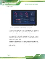
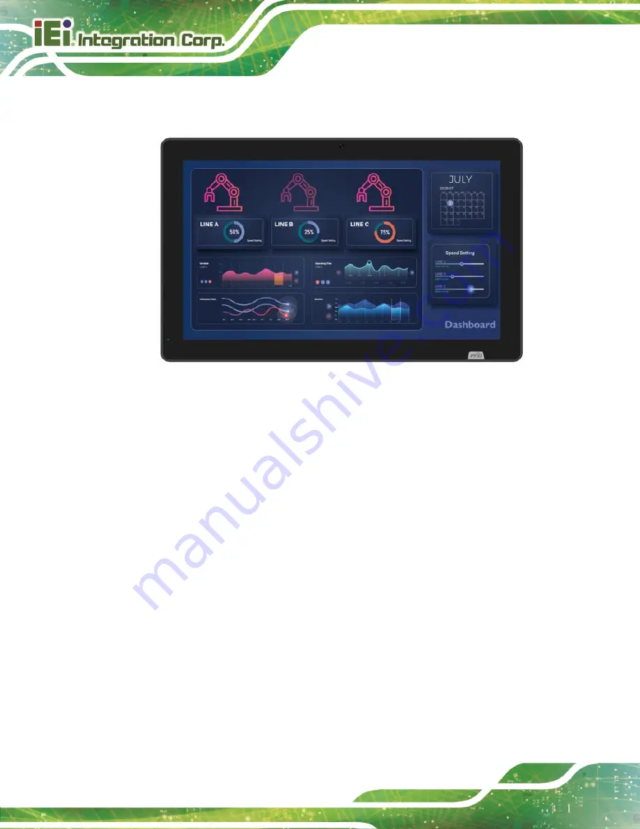
Figure 1-1: AFL3-W15C/W19C/W22C-ADLP Flat Bezel Panel PC 

The AFL3-W15C/W19C/W22C-ADLP series is a Intel® Alder Lake P 

Core™ powered flat 

bezel touchscreen panel PC with a rich variety of functions and peripherals. The flat-bezel 

design is ideal for easy and simplified integration into various applications. 

The Intel® Alder Lake P 

Core™ i7 / i5 / i3 & Celeron® is a System-On-Chip (SOC) that 

ensures  optimal  memory,  graphics,  and  peripheral  I/O  support.  The  system  comes  with 

8GB DDR4 SO-DIMMs 3200MHz memory ensuring smooth data throughputs with reduced 

bottlenecks and fast system access.   

One RS-232/422/485 serial port, one RS-232 serial port and four external USB 3.2 Gen 1 

ports  ensure  simplified  connectivity  to  a  variety  of  external  peripheral  devices.  Wi-Fi 

capabilities and two RJ-45 Ethernet connectors provide the system with smooth connection 

to an external LAN.   


Summary of Contents for AFL3-W15C-ADLP

Page 1: ...ME User Manual AFL3 W15C W19C W22C ADLP MODEL Flat Bezel Panel PC with Intel Alder Lake P Processor PCAP Touchscreen Four USB 3 2 Gen 1 Dual 2 5GbE LAN RS 232 422 485 Wi Fi 802 11a b g n ac ax and RoH...

Page 2: ...AFL3 W15C W19C W22C ADLP Page II MODEL NAME Revision Date Version Changes September 5 2023 1 00 Initial release...

Page 3: ...m overheating do not operate it in an area that exceeds the maximum operating temperature described in the user manual Vorsicht Um eine berhitzung des Systems zu vermeiden betreiben Sie es ausschlie l...

Page 4: ...a L uso di un altro tipo di adattatore pu causare rischio d incendio o esplosione Si prega di fare riferimento al manuale utente per le specifiche sull alimentazione Atenci n Utilice solamente el adap...

Page 5: ...er Wohnumgebung kann zu Funkst rungen f hren Warning L utilisation de cet quipement dans un environnement r sidentiel peut provoquer des interf rences radio Avvertenza Il funzionamento di questa appar...

Page 6: ...damages arising out of the use or inability to use the product or documentation even if advised of the possibility of such damages This document contains proprietary information protected by copyright...

Page 7: ...y CAUTION Cautionary messages should be heeded to help reduce the chance of losing data or damaging the product NOTE These messages inform the reader of essential but non critical information These me...

Page 8: ...IONS 12 1 9 1 AFL3 W15C ADLP Dimensions 12 1 9 2 AFL3 W19C ADLP Dimensions 13 1 9 3 AFL3 W22C ADLP Dimensions 14 2 UNPACKING 15 2 1 UNPACKING 16 2 2 PACKING LIST 16 2 3 OPTIONAL ITEMS 17 3 INSTALLATIO...

Page 9: ...tup 50 4 1 2 Using Setup 51 4 1 3 Getting Help 53 4 1 4 Unable to Reboot after Configuration Changes 53 4 1 5 BIOS Menu Bar 53 4 2 MAIN 54 4 3 ADVANCED 57 4 3 1 CPU Configuration 58 4 3 2 PCH FW Confi...

Page 10: ...TA 1 104 6 2 6 VR Power Debug Connector J1 J2 104 6 2 7 SPI Connector J_SPI1 105 6 2 8 EC Debug Port Connector EC_DBG1 105 6 2 9 Flash SPI ROM EC_FLASH1 105 6 2 10 Debug Connector DBG_PORT1 106 6 2 11...

Page 11: ...3 6 RS 232 422 485 DB 9 Serial Port COM1 113 6 3 7 RJ45 LAN Connector LAN 2 114 6 3 8 RJ45 LAN Connector LAN 1 114 6 3 9 RJ45 LAN Connector RJ IPMI1 115 6 3 10 Power Connector PWR3 115 6 4 PRECONFIGUR...

Page 12: ...ntion Screws 25 Figure 3 5 Lift the Aluminum Cover 26 Figure 3 6 M 2 Module Slot Location 27 Figure 3 7 Inserting the M 2 Module into the Slot at an Angle 27 Figure 3 8 Securing the M 2 Module 28 Figu...

Page 13: ...etention Screw Holes 43 Figure 3 26 Arm Mounting 44 Figure 3 27 Stand Mounting Stand A Bxx 45 Figure 3 28 Powering On the System 46 Figure 3 29 Reset Button Location 47 Figure 4 1 BIOS Starting Menu 5...

Page 14: ...1 J2 Pinouts 104 Table 6 8 SPI Connector J_SPI1 Pinouts 105 Table 6 9 EC Debug Connector EC_DBG1 Pinouts 105 Table 6 10 Flash SPI ROM EC_FLASH1 Pinouts 105 Table 6 11 Debug Connector DBG_PORT1 Pinouts...

Page 15: ...RJ 45 Serial Port COM2 Pinouts 113 Table 6 28 RS 232 422 485 DB 9 Serial Port COM1 Pinouts 113 Table 6 29 RJ45 LAN Connector LAN 2 114 Table 6 30 RJ45 LAN Connector LAN 1 114 Table 6 31 RJ45 LAN Conn...

Page 16: ...IOS Menu 13 RTC Wake Settings 69 BIOS Menu 14 Serial Port Console 71 BIOS Menu 15 COM Console Redirection Settings 72 BIOS Menu 16 Network Stack Configuration 74 BIOS Menu 17 NVMe Configuration 75 BIO...

Page 17: ...AFL3 W15C W19C W22C ADLP Page 1 1 Introduction Chapter 1...

Page 18: ...he Intel Alder Lake P Core i7 i5 i3 Celeron is a System On Chip SOC that ensures optimal memory graphics and peripheral I O support The system comes with 8GB DDR4 SO DIMMs 3200MHz memory ensuring smoo...

Page 19: ...l Core i7 1260P AFL3 W22C ADLP i3 8G R10 21 5 Intel Core i3 1220P AFL3 W22C ADLP i5 8G R10 Intel Core i5 1240P AFL3 W22C ADLP i7 8G R10 Intel Core i7 1260P Table 1 1 Model Variations 1 3 Features The...

Page 20: ...a PC ABS plastic frame Figure 1 2 Figure 1 2 Front View There is a power LED indicator located on the front panel The status descriptions of the power LED indicator are listed below Off power cord not...

Page 21: ...AFL3 W15C W19C W22C ADLP Page 5 1 5 Bottom Panel The bottom panel of the AFL3 W15C W19C W22C ADLP has the following connectors and switches Figure 1 3 AFL3 W15C W19C W22C ADLP Bottom Panel...

Page 22: ...r panel has two speakers and retention screw holes that support VESA mounting The rear panel also has several retention screw holes for installing the optional barcode scanner and magnetic stripe card...

Page 23: ...Window modules are for ATO assembly to order only Part No Description Supported Model iM2 LVDS01 R10 M 2 to Single Dual Channel LVDS Module AFL3 W15C ADLP AFL3 W19C ADLP AFL3 W22C ADLP iM2 CAN 2P R10...

Page 24: ...H x V mm 0 240 x 0 240 0 240 x 0 240 0 248 x 0 248 Viewing Angle H V 170 170 170 170 178 178 Backlight MTBF 50 000 hrs 50 000 hrs 50 000 hrs Backlight LED LED LED Touchscreen PCAP with USB interface a...

Page 25: ...Mounting Panel wall rack stand or arm mounting Front Panel Color Black C Dimensions W x H x D mm 396 x 250 x 64 472 x 292 x 68 528 x 336 x 68 Storage Temperature 20 C 60 C Humidity 10 95 non condensin...

Page 26: ...AFL3 W15C W19C W22C ADLP Page 10 1 x Power switch 1 x AT ATX switch 1 x ClearCMOS Button 1 x Reset button 1 x 12V DC Jack Table 1 3 System Specifications...

Page 27: ...luetooth BR EDR 2402 2480 10 Bluetooth LE 2402 2480 10 Table 1 4 WLAN Bluetooth Frequency Range and Power WARNING This equipment complies with CE radiation exposure limits set forth for an uncontrolle...

Page 28: ...19C W22C ADLP Page 12 1 9 Dimensions The following sections list the dimensions of each model 1 9 1 AFL3 W15C ADLP Dimensions The AFL3 W15C ADLP dimensions are shown below Figure 1 6 AFL3 W15C ADLP Di...

Page 29: ...AFL3 W15C W19C W22C ADLP Page 13 1 9 2 AFL3 W19C ADLP Dimensions The AFL3 W19C ADLP dimensions are shown below Figure 1 7 AFL3 W19C ADLP Dimensions mm...

Page 30: ...AFL3 W15C W19C W22C ADLP Page 14 1 9 3 AFL3 W22C ADLP Dimensions The AFL3 W22C ADLP dimensions are shown below Figure 1 8 AFL3 W22C ADLP Dimensions mm...

Page 31: ...AFL3 W15C W19C W22C ADLP Page 15 2 Unpacking Chapter 2...

Page 32: ...Only cut deep enough to break the tape Step 2 Open the outside box Step 3 Carefully cut the tape sealing the box Only cut deep enough to break the tape Step 4 Open the inside box Step 5 Lift the panel...

Page 33: ...y Item Image 1 AFL3 W15C W19C W22C ADLP panel PC 1 96 W power adapter P N 63040 010096 100 RS 1 Power cord 4 Screws M4 6 for VESA mounting 4 Screws M3 4 for HDD installation 2 3 Optional Items The fol...

Page 34: ...18 Item and Part Number Image Panel mounting kit P N AFL3PK W15A R10 for W15C P N AFL3PK W19C R10 for W19C W22C Rack mounting kit P N AFL3RK W15B R10 for W15C Arm P N ARM 11 RS Arm P N ARM 31 RS Stand...

Page 35: ...art Number Image Stand for VESA 75 VESA 100 P N STAND C19 R10 Magnetic card reader P N AFL3P W10MSR U R10 Barcode scanner P N AFL3 2D R10 If any of these items are missing or damaged contact the distr...

Page 36: ...AFL3 W15C W19C W22C ADLP Page 20 3 Installation Chapter 3...

Page 37: ...can help to prevent ESD from damaging the board Self grounding Before handling the board touch any grounded conducting material During the time the board is handled frequently touch any conducting mat...

Page 38: ...l an M 2 module or a HDD Step 3 Configure the system Step 4 Connect peripheral devices to the flat bezel panel PC Step 5 Mount the flat bezel panel PC Step 0 3 4 Removing the Back Covers To access the...

Page 39: ...FL3 W15C W19C W22C ADLP Step 3 Remove the retention screws from the internal aluminum cover Two types of screw are used for securing the aluminum cover See the following diagrams for detail Be aware o...

Page 40: ...AFL3 W15C W19C W22C ADLP Page 24 Figure 3 2 AFL3 W15C ADLP Aluminum Cover Retention Screws Figure 3 3 AFL3 W19C ADLP Aluminum Cover Retention Screws...

Page 41: ...ention Screws Step 4 Lift the aluminum cover off the AFL3 W15C W19C W22C ADLP A thermal pad is attached under the center of the aluminum cover To easily remove the cover turn the cover in a clockwise...

Page 42: ...as an M 2 2280 M key slot PCIe signal To install an M 2 module into the AFL3 W15C W19C W22C ADLP please follow the steps below Step 1 Remove the plastic back cover and the internal aluminum cover See...

Page 43: ...3 Line up the notch on the card with the notch on the slot Slide the M 2 card into the socket at an angle of about 20 Figure 3 7 Figure 3 7 Inserting the M 2 Module into the Slot at an Angle Step 4 Se...

Page 44: ...6 HDD Installation To install the HDD into the system please follow the steps below Step 1 Remove the plastic back cover and the internal aluminum cover See Section 3 4 above Step 2 Remove the four H...

Page 45: ...HDD To do this align the four retention screw holes in the both sides of the HDD bracket with the retention screw holes on the sides of the HDD Insert four retention screws into the HDD bracket Figur...

Page 46: ...screws Figure 3 11 HDD Installation Step 6 Replace the internal aluminum cover and the plastic back cover Step 0 3 7 Clear CMOS If the AFL3 W15C W19C W22C ADLP fails to boot due to improper BIOS setti...

Page 47: ...witch Location 3 8 1 AT Power Mode With the AT mode selected the power is controlled by a central power unit rather than a power switch The AFL3 W15C W19C W22C ADLP panel PC turns on automatically whe...

Page 48: ...t of Sale POS Advertising terminal 3 9 Mounting the System The methods of mounting the AFL3 W15C W19C W22C ADLP are listed below Wall mounting Panel mounting Rack mounting Arm mounting Stand mounting...

Page 49: ...Step 6 Insert the four monitor mounting screws provided in the wall mount kit into the four screw holes on the real panel of the flat bezel panel PC and tighten until the screw shank is secured agains...

Page 50: ...gently pull the monitor downwards until the monitor rests securely in the slotted holes Ensure that all four of the mounting screws fit snugly into their respective slotted holes NOTE In the diagram...

Page 51: ...ounting To mount the AFL3 W15C W19C W22C ADLP flat bezel panel PC into a panel please follow the steps below Step 1 Select the position on the panel to mount the panel PC Step 2 Cut out a section corr...

Page 52: ...ge 36 Figure 3 17 AFL3 W15C ADLP Cutout Dimensions Figure 3 18 AFL3 W19C ADLP Cutout Dimensions Figure 3 19 AFL3 W22C ADLP Cutout Dimensions Step 3 Slide the panel PC through the hole until the frame...

Page 53: ...Spring Install a spring onto the screw 2 Nut Tighten a nut until the spring is compressed enough for plastic cap 3 Plastic cap Tighten a plastic cap onto the end of screw thread Step 5 Repeat Step 4...

Page 54: ...f the panel PC by inserting the four retention screws into the VESA mounting holes and tightening them Figure 3 21 Figure 3 21 Securing Panel Mounting Brackets NOTE The panel mounting kit described in...

Page 55: ...W22C ADLP is installed Step 1 Slide the rear chassis of the AFL3 W15C W19C W22C ADLP panel PC through the rack cabinet bracket until the frame is flush against the front of the bracket Step 2 Insert a...

Page 56: ...holes on the rear of the panel PC Step 5 Secure the two rack mounting brackets to the rear of the panel PC by inserting the four retention screws into the VESA mounting holes and tightening them Figur...

Page 57: ...bracket to the front of the rack or cabinet NOTE The rack mounting kit described in this section is an optional item To purchase it please contact an IEI sales representative 3 9 4 Arm Mounting The AF...

Page 58: ...sure that it is VESA compliant and that the arm has a 75 mm or a 100 mm interface pad If the mounting arm is not VESA compliant it cannot be used to support the AFL3 W15C W19C W22C ADLP flat bezel pan...

Page 59: ...Figure 3 25 Arm Mounting Retention Screw Holes Step 4 Secure the AFL3 W15C W19C W22C ADLP to the interface pad by inserting four retention screws through the mounting arm interface pad and into the AF...

Page 60: ...mounting kit please follow the steps below Step 1 Locate the screw holes on the rear of the AFL3 W15C W19C W22C ADLP This is where the bracket will be attached Step 2 Align the bracket with the screw...

Page 61: ...he power cord to the power adapter Connect the other end of the power cord to a power source Step 2 Connect the power adapter to the power connector of the AFL3 W15C W19C W22C ADLP Step 3 Locate the p...

Page 62: ...Figure 3 28 Powering On the System 3 11 Reset the System The reset button enables user to reboot the system when the system is turned on The reset button location is shown in Figure 3 29 Press the re...

Page 63: ...world com Type the model name and press Enter to find all the relevant software utilities and documentation 3 12 1 Driver Download To download drivers from IEI Resource Download Center follow the step...

Page 64: ...the following window You can download the entire ISO file or click the small arrow to find an individual driver and click the file name to download NOTE To install software from the downloaded ISO im...

Page 65: ...AFL3 W15C W19C W22C ADLP Page 49 4 BIOS Setup Chapter 4...

Page 66: ...notice 4 1 1 Starting Setup The UEFI BIOS is activated when the computer is turned on The setup program can be activated in one of two ways 1 Using keyboard Press the DEL or F2 as soon as the system...

Page 67: ...e item on the right hand side Increase the numeric value or make changes Decrease the numeric value or make changes Page Up Move to the previous page Page Dn Move to the next page Esc Main Menu Quit a...

Page 68: ...screen Button Function Previous Values Load the last value you set Optimized Defaults Load the factory default values in order to achieve the best performance Back Return to the previous menu Soft kbd...

Page 69: ...ade CMOS defaults Use the jumper described in Section 3 7 4 1 5 BIOS Menu Bar The menu bar on top of the BIOS screen has the following main items Main Changes the basic system configuration Advanced C...

Page 70: ...C W19C W22C ADLP Page 54 4 2 Main The Main BIOS menu BIOS Menu 1 BIOS Menu 2 appears when the BIOS Setup program is entered The Main menu gives an overview of the basic system information BIOS Menu 1...

Page 71: ...d BIOS vendor Core Version Current BIOS version Compliancy Current UEFI PI version Project Version the board version Build Date and Time Date the current BIOS version was made Access Level Current BIO...

Page 72: ...al Memory Total Memory in the System Memory Frequency Displays the Data Rate of Memory PCH Information The PCH Information lists a brief summary of the PCH The fields in PCH Information cannot be chan...

Page 73: ...ime option to set the system time Manually enter the hours minutes and seconds 4 3 Advanced Use the Advanced menu BIOS Menu 3 to configure the CPU and peripheral devices through the following sub menu...

Page 74: ...ADLP Page 58 4 3 1 CPU Configuration Use the CPU Configuration menu BIOS Menu 4 BIOS Menu 5 BIOS Menu 6 to view detailed CPU specifications or enable the Intel Virtualization Technology BIOS Menu 4 CP...

Page 75: ...AFL3 W15C W19C W22C ADLP Page 59 BIOS Menu 5 CPU Configuration 2 3 BIOS Menu 6 CPU Configuration 3 3...

Page 76: ...CPU to go to C states when it s not 100 utilized Turbo Mode Enabled Use the Turbo Mode option to enable or disable Turbo Mode which requires Intel Speed Step or Intel Speed Shift to be available and e...

Page 77: ...are looked at together When both are 0 0 Pcode will enable all cores All DEFAULT Enable all cores in the processor package 0 Enable zero cores in the processor package 1 Enable one core in the proces...

Page 78: ...it and TDP Limit If value is 0 BIOS will program TDP value Power Limit 2 Use the Power Limit 2 to set Power Limit in Milli Watts BIOS will round to the nearest 1 8W when programming If the value is 0...

Page 79: ...to configure settings Intel AMT Supported configurations BIOS Menu 7 PCH FW Configuration Intel AMT Enable Use the Intel AMT option to enable or disable access MEBx Setup supported Disabled Disables...

Page 80: ...Computing Security Device Support Enable Use the Security Device Support option to configure support for the TCG EFI Protocol and INT1A Disable Security Device support is disabled Enable DEFAULT Secur...

Page 81: ...e parallel ports and serial ports BIOS Menu 9 IT5571 IO Configuration IT5571 Super IO Configuration The IT5571 Super IO Configuration lists a brief summary of the Super IO Chip information The items s...

Page 82: ...ial Port 1 Configuration Serial Port Enabled Use the Serial Port option to enable or disable the serial port Disabled Disable the serial port Enabled DEFAULT Enable the serial port Device Settings The...

Page 83: ...d Use the Serial Port option to enable or disable the serial port Disabled Disable the serial port Enabled DEFAULT Enable the serial port Device Settings The Device Settings option shows the serial po...

Page 84: ...t mode is RS 422 The serial port mode is RS 485 4 3 5 IT5571 H W Monitor The IT5571 H W Monitor menu BIOS Menu 12 displays the system temperature and CPU fan speed BIOS Menu 12 IT5571 H W Monitor PC H...

Page 85: ...toryset Tcc activation temprature at which the Thermal Control Circuit must be activated Tcc will be activated at Tcc Activation Temp Tcc Activation Offset Tcc Activation Offset range is 0 to 63 4 3 6...

Page 86: ...k RTC cannot generate a wake event Enabled If selected the Wake up every day option appears allowing you to enable to disable the system to wake every day at the specified time Besides the following o...

Page 87: ...otely by re directing keyboard input and text output through the serial port BIOS Menu 14 Serial Port Console Console Redirection Disabled Use Console Redirection option to enable or disable the conso...

Page 88: ...al Type ANSI Use the Terminal Type option to specify the remote terminal type VT100 The target terminal type is VT100 VT100 The target terminal type is VT100 VT UTF8 The target terminal type is VT UTF...

Page 89: ...the data bits for detecting the transmission errors None DEFAULT No parity bit is sent with the data bits Even The parity bit is 0 if the number of ones in the data bits is even Odd The parity bit is...

Page 90: ...work Stack Configuration Use the Network Stack option to enable or disable the UEFI Network Stack BIOS Menu 16 Network Stack Configuration Network Stack Disabled Disabled Disables UEFI Network Stack E...

Page 91: ...AFL3 W15C W19C W22C ADLP Page 75 4 3 9 NVMe Configuration Use the NVMe Configuration BIOS Menu 17 menu to display the NVMe controller and device information BIOS Menu 17 NVMe Configuration...

Page 92: ...t Use the Chipset menu BIOS Menu 18 to access the PCH IO and System Agent SA configuration menus WARNING Setting the wrong values for the Chipset BIOS selections in the Chipset BIOS menu may cause the...

Page 93: ...Agent SA Configuration menu BIOS Menu 19 to configure the System Agent SA parameters BIOS Menu 19 System Agent SA Configuration VT d Enabled Use the VT d option to enable or disable the VT d capabili...

Page 94: ...AFL3 W15C W19C W22C ADLP Page 78 4 4 1 1 Memory Configuration Use the Memory Configuration submenu BIOS Menu 20 to view memory information BIOS Menu 20 Memory Configuration...

Page 95: ...5C W19C W22C ADLP Page 79 4 4 1 2 Graphics Configuration Use the Graphics Configuration BIOS Menu 21 menu to view configuration of the video device connected to the system BIOS Menu 21 Graphics Config...

Page 96: ...80 4 4 1 3 VMD setup menu Use the VMD Configuration to Enable or Disable to VMD controller BIOS Menu 22 VMD setup menu Enable VMD Controller Disabled Disabled DEFAULT Disable the VMD controller Enabl...

Page 97: ...port settings BIOS Menu 23 PCI Express Configuration M2_M1 Enabled Use M2_M1 to control the PCI Express root port Enabled DEFAULT Enable the M2_M1 Disabled Disable the M2_M1 PCIe Speed Auto Use the PC...

Page 98: ...trol the PCI Express root port Disabled Disable the M2_M2 Enabled DEFAULT Enable the M2_M2 PCIe Speed Auto Use the PCIe Speed option to specify the PCI Express port speed Configuration options are lis...

Page 99: ...ction BIOS option to show the power mode state is ATX Restore AC Power Loss Last State Use the Restore AC Power Loss BIOS option to specify what state the system returns to if there is a sudden loss o...

Page 100: ...ower consumption when the system is off USB Power SW1 5V DUAL Use the USB Power SW1 BIOS option to configure the USB power source for the corresponding USB connectors 5V DUAL DEFAULT Sets the USB powe...

Page 101: ...enu 25 PCI Express Configuration M2_E1 Enabled Use M2_E1 to control the PCI Express root port Enabled DEFAULT Enable the M2_E1 Disabled Disable the M2_E1 PCIe Speed Auto Use the PCIe Speed option to s...

Page 102: ...Express root port Disabled Disable the M2_B Enabled DEFAULT Enable the M2_B PCIe Speed Auto Use the PCIe Speed option to specify the PCI Express port speed Configuration options are listed below Auto...

Page 103: ...u 26 to configure the High Definition Audio codec BIOS Menu 26 HD Audio Configuration HD Audio Enabled Use the HD Audio BIOS option to enable or disable the High Definition Audio controller Disabled T...

Page 104: ...iguration SATA Controller s Enabled Use the SATA Controller s option to configure the SATA controller s Enabled DEFAULT Enables the on board SATA controller s Disabled Disables the on board SATA contr...

Page 105: ...AFL3 W15C W19C W22C ADLP Page 89 4 5 Security Use the Security menu BIOS Menu 28 BIOS Menu 29 to set system and user passwords BIOS Menu 28 Security 1 2...

Page 106: ...9C W22C ADLP Page 90 BIOS Menu 29 Security 2 2 Administrator Password Use the Administrator Password to set or change a administrator password User Password Use the User Password to set or change a us...

Page 107: ...ck State BIOS option to specify if the number lock setting must be modified during boot up On DEFAULT Allows the Number Lock on the keyboard to be enabled automatically when the computer system boots...

Page 108: ...D on the keyboard lights up when the Number Lock is engaged Boot Option Priority Use the Boot Option Priority function to set the system boot sequence from the available devices The drive sequence als...

Page 109: ...saving the changes made to the BIOS configuration setup program Restore Defaults Use the Restore Defaults option to load the optimal default values for each of the parameters on the Setup menus F3 ke...

Page 110: ...AFL3 W15C W19C W22C ADLP Page 94 5 System Maintenance Chapter 5...

Page 111: ...C W19C W22C ADLP Dry climates are especially susceptible to ESD It is therefore critical that whenever the AFL3 W15C W19C W22C ADLP is accessed internally or any other electrical component is handled...

Page 112: ...out on the system make sure the system is turned off 5 4 SO DIMM Module Replacement The AFL3 W15C W19C W22C ADLP has one SO DIMM module installed To replace the SO DIMM module follow the instructions...

Page 113: ...he spring retainer clips outward from the socket Step 6 Grasp the DDR4 memory module by the edges and carefully pull it out of the socket Step 7 Install the new DDR4 memory module by pushing it into t...

Page 114: ...Step 9 Reinstall the internal aluminum cover and the plastic back cover using the previously removed retention screws Step 0 WARNING Failing to reinstall the cover may result in permanent damage to t...

Page 115: ...AFL3 W15C W19C W22C ADLP Page 99 6 Interface Connectors Chapter 6...

Page 116: ...re 6 1 The connector pinouts for these connectors are listed in the following sections Figure 6 1 Main Board Layout Diagram 6 2 Internal Peripheral Connectors Internal peripheral connectors are found...

Page 117: ...Connector 22 pin wafer EC_DBG1 Flash SPI ROM 4 pin wafer EC_FLASH1 Debug Connector 6 pin Header DBG_PORT1 Audio Speaker Connector 2 pin wafer SP_CN_L SP_CN_R IPMI Connector 67 pin wafer IPMI1 Power LE...

Page 118: ...N C 27 GND 28 N C 29 PCIE_TXN2 30 N C 31 PCIE_TXP2 32 N C 33 GND 34 N C 35 PCIE_RXN2 36 N C 37 PCIE_RXP2 38 N C 39 GND 40 N C 41 PCIE_TXN1 42 N C 43 PCIE_TXP1 44 N C 45 GND 46 N C 47 PCIE_RXN1 48 N C...

Page 119: ...J 5 GND 6 GND Table 6 3 Set Voltage Connector INV1 Pinouts 6 2 3 LVDS VDD Power Selection J_PANEL1 J_PW1 J_PANEL1 PIN NO DESCRIPTION 1 2 LVDS Panel 2 3 VDC Panel J_PW1 PIN NO DESCRIPTION 1 2 LVDS Pane...

Page 120: ...2 5 SATA Connector SATA 1 PIN NO DESCRIPTION PIN NO DESCRIPTION 1 GND 2 GND 3 GND 4 GND 5 GND 6 GND 7 5V 8 5V 9 5V 10 5V 11 5V 12 N C 13 N C 14 GND 15 RX 16 RX 17 GND 18 TX 19 TX 20 GND Table 6 6 SATA...

Page 121: ...C Debug Port Connector EC_DBG1 PIN NO DESCRIPTION PIN NO DESCRIPTION 1 KSI0 2 KSO0 3 KSO1 4 KSO2 5 KSO3 6 KSO4 7 KSO5 8 KSO6 9 KSO7 10 KSO8 11 KSO9 12 KSO10 13 KSO12 14 KSL1 15 KSO11 16 KSI2 17 KSI3 1...

Page 122: ...NFIG_3 2 3 3V_2 3 GND_3 4 3 3V_4 5 GND_5 6 FULL_CARD_POWER _OFF_N 7 SUD_D 8 W_DISABLE_N 9 SUB_D 10 GPIO_9 DAS DSS_N 11 GDN_11 12 NC 5 13 NC 1 14 NC 6 15 NC 2 16 NV 7 17 NV 3 18 NC 8 19 NC 4 20 GPIO_5...

Page 123: ...COEX1 65 ANTCTL3 66 SIM_DETECT 67 PESET_N 68 SSCLIK 69 PESET_OC PCIE GND SATA 70 3 3V_70 71 GND_71 72 3 3V_72 73 GND_73 74 3 3V_74 75 USB3 0IND OTHER Table 6 12 IPMI1 Connector pinouts 6 2 12 Power LE...

Page 124: ..._L 29 GND 30 CLK1P_L 31 CLK1M_L 32 GND 33 A2P_L 34 A2M_L 35 GND 36 A1P_L 37 A1M_L 38 GND 39 A0P_L 40 A0M_L Table 6 14 LVDS Panel Connector LVDS1 Pinouts 6 2 14 EDP Connector EDP1 PIN NO DESCRIPTION PI...

Page 125: ...6 2 15 CPU Fan Connector CPU_FAN1 PIN NO DESCRIPTION PIN NO DESCRIPTION 1 GND 2 12V 3 FANIO 4 PWM Table 6 16 CPU Fan Connector CPU_FAN1 Pinouts 6 2 16 USB Connector CAMERA_USB2 PIN NO DESCRIPTION PIN...

Page 126: ...3 HUB_D3F 4 GND Table 6 19 USB Connector RFID_USB1 6 2 19 USB Connector DMIC1 PIN NO DESCRIPTION PIN NO DESCRIPTION 1 DMIC_CLK 2 DMIC_DATA 3 3 3V 4 GND Table 6 20 USB Connector DMIC1 6 2 20 USB Conne...

Page 127: ...nectors USB 3 2 Gen 1 port USB3_CON2 USB3_CON1 RS 232 serial port D sub 9 COM2 RS 232 422 485 serial port D sub 9 COM1 RJ45 LAN Connector I225 RJ 45 LAN1 RJ45 LAN Connector I225 RJ 45 LAN2 RJ45 LAN Co...

Page 128: ...ESCRIPTION PIN NO DESCRIPTION 1 5Vsus 10 5Vsus 2 DATA0 11 DATA1 3 DATA0 12 DATA1 4 GND 13 GND 5 SSRX0 14 SSRX1 6 SSRX0 15 SSRX1 7 GND 16 GND 8 SSTX0 17 SSTX1 9 SSTX0 18 SSTX1 Table 6 25 USB 3 2 Gen 1...

Page 129: ...NO DESCRIPTION PIN NO DESCRIPTION 1 NDCD2 6 NDSR2 2 NSIN2 7 NRTS2 3 NSOUT2 8 NCTS2 4 NRTS2 9 XRI2 5 GND Table 6 27 RS 232 RJ 45 Serial Port COM2 Pinouts 6 3 6 RS 232 422 485 DB 9 Serial Port COM1 PIN...

Page 130: ...N A 14 LINK 1000 3 3V sus 6 N A 15 GND 7 MDI2 17 GND 8 MDI2 18 N A 9 MDI3 19 N A Table 6 29 RJ45 LAN Connector LAN 2 6 3 8 RJ45 LAN Connector LAN 1 PIN NO DESCRIPTION PIN NO DESCRIPTION 1 MDI0 10 MDI3...

Page 131: ...I1 12 ACT 1 4 MDI1 13 LINK 1000 3 3V sus 5 N A 14 LINK 1000 3 3V sus 6 N A 15 GND 7 MDI2 17 GND 8 MDI2 18 N A 9 MDI3 19 N A Table 6 31 RJ45 LAN Connector RJ IPMI1 6 3 10 Power Connector PWR3 6 4 Preco...

Page 132: ...DS Voltage Selection Jumper J_VLVDS1 Settings 6 4 2 LVDS Panel Resolution Selection Jumper SW1 ON 0 OFF 1 Single S Dual D SW1 4 3 2 1 Description 0000 800x600 18bit S Default 0001 1024x768 18bit S 001...

Page 133: ...AFL3 W15C W19C W22C ADLP Page 117 SW1 4 3 2 1 Description Table 6 35 LVDS Resolution Selection Jumper SW1 Settings...

Page 134: ...AFL3 W15C W19C W22C ADLP Page 118 Appendix A A Regulatory Compliance...

Page 135: ...ons functionality it also complies with the requirements of the Radio Equipment Directive 2014 53 EU Hereby IEI INTEGRATION CORP declares that the radio equipment type AFL3 W15C ADLP AFL4 W19C ADLP AF...

Page 136: ...los requisitos esenciales y cualesquiera otras disposiciones aplicables o exigibles de la Directiva 2014 53 EU Greek IEI Integration Corp 2014 53 EU Fran ais French IEI Integration Corp d clare que l...

Page 137: ...a Directiva 2014 53 EU Rom na Romanian IEI Integration Corp declar c acest echipament este in conformitate cu cerin ele esen iale i cu celelalte prevederi relevante ale Directivei 2014 53 EU Slovensko...

Page 138: ...erference at his own expense Federal Communication Commission Interference Statement This equipment has been assembled with components that comply with the limits for a Class B digital device pursuant...

Page 139: ...entally Friendly Use Period EFUP This is an estimate of the number of years that these substances would not leak out or undergo abrupt change This product may contain replaceable sub assemblies compon...

Page 140: ...AFL3 W15C W19C W22C ADLP Page 124 B Safety Precautions Appendix B...

Page 141: ...vent the risk of electric shock make sure power cord is unplugged from wall socket To fully disengage the power to the unit please disconnect the power cord from the AC outlet Refer servicing to quali...

Page 142: ...nents including the AFL3 W15C W19C W22C ADLP Dry climates are especially susceptible to ESD It is therefore critical that whenever the AFL3 W15C W19C W22C ADLP is opened and any of the electrical comp...

Page 143: ...is classified as electronic device in terms of the European Directive 2012 19 EU WEEE and must not be disposed of as domestic garbage EU wide legislation as implemented in each Member State requires...

Page 144: ...er spray or squirt liquids directly onto any other components To clean the LCD panel gently wipe it with a piece of soft dry cloth or a slightly moistened cloth The interior of the device does not req...

Page 145: ...not recommended when cleaning the device as they may damage the plastic parts Vacuum cleaner Using a vacuum specifically designed for computers is one of the best methods of cleaning the device Dust...

Page 146: ...AFL3 W15C W19C W22C ADLP Page 130 C BIOS Menu Options Appendix C...

Page 147: ...1 Power Limit 1 62 Power Limit 2 62 Power Limit 1 Time Window 62 Intel AMT Enable 63 Security Device Support Enable 64 Pending Operation None 64 IT5571 Super IO Configuration 65 Serial Port Enabled 66...

Page 148: ...SB Power SW2 5V DUAL 84 M2_B IPMI Enabled 86 PCIe Speed Auto 86 HD Audio Enabled 87 SATA Controller s Enabled 88 SATA Mode Selection AHCI 88 Serial ATA Port 0 Empty 88 Serial ATA Port 1 Empty 88 Admin...

Page 149: ...AFL3 W15C W19C W22C ADLP Page 133 Appendix D D Watchdog Timer...

Page 150: ...15H AH 6FH Sub function AL 2 Sets the Watchdog Timer s period BL Time out value Its unit second is dependent on the item Watchdog Timer unit select in CMOS setup Table D 1 AH 6FH Sub function Call sub...

Page 151: ...is not deactivated the system will automatically restart after the Timer has finished its countdown EXAMPLE PROGRAM INITIAL TIMER PERIOD COUNTER W_LOOP MOV AX 6F02H setting the time out value MOV BL 3...

Page 152: ...AFL3 W15C W19C W22C ADLP Page 136 Appendix E E Error Beep Code...

Page 153: ...not found 4 Recovery failed 4 S3 Resume failed 7 Reset PPI is not available E 2 DXE Beep Codes Number of Beeps Description 1 Invalid password 4 Some of the Architectural Protocols are not available 5...

Page 154: ...AFL3 W15C W19C W22C ADLP Page 138 Appendix F F Hazardous Materials Disclosure...

Page 155: ...PBB Polybrominated Diphenyl Ethers PBDE Bis 2 ethylhexyl phthalate DEHP Butyl benzyl phthalate BBP Dibutyl phthalate DBP Diisobutyl phthalate DIBP Housing O O O O O O O O O O Printed Circuit Board O O...

Page 156: ...W22C ADLP Page 140 F 2 China RoHS RoHS RoHS Pb Hg Cd CR VI PBB PBDE O O O O O O O O O O O O O O O O O O O O O O O O O O O O O O O O O O O O O O O O O O O SJ T11364 2014 GB T26572 2011 X SJ T11364 2014...

Reviews: