background image


AFL-W19A/17D/W15A-N270 Panel PC 

Page 23

COM3 TX Function Select 

Description 

Short 1 – 3   

RS-422 

Short 2 – 4 

RS-422 

Short 3 – 5 

RS-485 

Short 4 – 6 

RS-485 

Table 2-9: COM3 TX Function Select Jumper Settings 

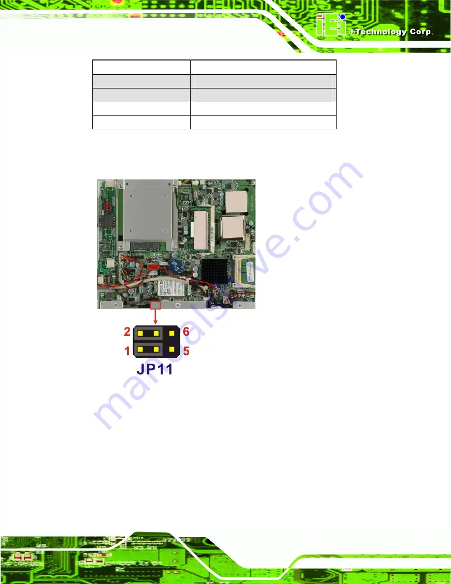
The COM3 TX Function Select jumper location is shown in Figure 2-12 below. 


Figure 2-12: COM3 TX Function Select Jumper Pinout Locations 

2.5.8 COM3 RS-232/422/485 Serial Port Select Jumper 

Jumper Label: 

JP10 

Jumper Type: 

12-pin header (four 3-pin headers combined) 

Jumper Settings: 

See Table 2-10 

Jumper Location: 

See Figure 2-13 

Summary of Contents for AFL-W15A-N270

Page 1: ...N270 Panel PC Page i IEI Technology Corp User Manual MODEL AFL W19A 17D W15A N270 Panel PC with Touch Screen Intel CPU Gigabit Ethernet USB Audio RS 232 422 485 SATA RoHS Compliant IP64 Protection Rev...

Page 2: ...o AFL W19A 17D W15A N270 29 February 2012 2 20 Updated for R22 version Bluetooth function optional 29 June 2011 1 06 Added battery disposal warning message in Appendix A 24 June 2010 1 05 Minor update...

Page 3: ...mages arising out of the use or inability to use the product or documentation even if advised of the possibility of such damages This document contains proprietary information protected by copyright A...

Page 4: ...270 Dimensions 9 2 INSTALLATION 10 2 1 UNPACK THE PANEL PC 11 2 2 PACKING LIST 12 2 3 HARD DRIVE INSTALLATION 13 2 4 COMPACTFLASH INSTALLATION 14 2 4 1 AFL 17D N270 CompactFlash Installation 15 2 4 2...

Page 5: ...tion 39 2 7 4 VGA Monitor Connection 40 2 8 POWER CONNECTION 41 2 9 DRIVER INSTALLATION 41 3 BIOS SETUP 43 3 1 INTRODUCTION 44 3 1 1 Starting Setup 44 3 1 2 Using Setup 44 3 1 3 Getting Help 45 3 1 4...

Page 6: ...5 3 8 EXIT 86 4 SYSTEM MAINTENANCE 88 4 1 SYSTEM MAINTENANCE INTRODUCTION 89 4 2 MOTHERBOARD REPLACEMENT 89 4 3 COVER REMOVAL 89 4 4 MEMORY MODULE REPLACEMENT 90 A SAFETY PRECAUTIONS 92 A 1 SAFETY PRE...

Page 7: ...AFL W19A 17D W15A N270 Panel PC Page vii F HAZARDOUS MATERIALS DISCLOSURE 112 F 1 HAZARDOUS MATERIALS DISCLOSURE TABLE FOR IPB PRODUCTS CERTIFIED AS ROHS COMPLIANT UNDER 2002 95 EC WITHOUT MERCURY 113...

Page 8: ...CompactFlash Install 16 Figure 2 8 CF Card Setup Jumper Location 19 Figure 2 9 Clear CMOS Jumper 20 Figure 2 10 COM1 and COM3 Pin 9 Setting Jumper Locations 21 Figure 2 11 COM3 RX Function Select Jump...

Page 9: ...re 2 30 LAN Connection 38 Figure 2 31 Serial Device Connector 39 Figure 2 32 USB Device Connection 40 Figure 2 33 VGA Connector 41 Figure 4 1 Back Cover Retention Screws 90 Figure 4 2 DDR SO DIMM Modu...

Page 10: ...s 19 Table 2 5 Clear CMOS Jumper Settings 20 Table 2 6 COM1 Pin 9 Setting Jumper Settings 21 Table 2 7 COM3 Pin 9 Setting Jumper Settings 21 Table 2 8 COM3 RX Function Select Jumper Settings 22 Table...

Page 11: ...10 APM Configuration 63 BIOS Menu 11 Remote Access Configuration 65 BIOS Menu 12 USB Configuration 69 BIOS Menu 13 USB Mass Storage Device Configuration 71 BIOS Menu 14 PCI PnP Configuration 73 BIOS M...

Page 12: ...AFL W19A 17D W15A N270 Panel PC Page 1 Chapter 1 1 Introduction...

Page 13: ...s excluding the power supply contained inside the casing allowing a completely interactive panel PC with only a single power cable Network access is enabled through an 802 11b g n wireless adapter Wir...

Page 14: ...n Wireless LAN Gigabit Ethernet Bluetooth optional IP64 protection RoHS compliant 1 4 External Overview The AFL W19A 17D W15A N270 consists of a screen and rear panel that covers the back sides and to...

Page 15: ...W19A 17D W15A N270 Panel PC Page 4 Figure 1 2 Front Panel 1 4 2 Rear Panel The rear panel provides access to retention screw holes that support the wall mounting Refer to Figure 1 3 Figure 1 3 Rear Pa...

Page 16: ...h 1 x Power input 12 V 1 x Reset button 1 x RS 232 1 x RS 232 422 485 4 x USB ports 1 x VGA port Figure 1 4 Bottom Panel 1 5 Internal Overview All the components are contained under the rear panel The...

Page 17: ...llion Pixel Pitch 0 252 x 0 252 0 264 x 0 264 0 2835 x 0 2835 Viewing Angle H V 170 160 160 160 170 160 Backlight MTBF 50000 50000 30000 Touch Screen 5 wire resistive touch panel I O 2 x Gigabit LAN 1...

Page 18: ...AFL W19A 17D W15A N270 Panel PC Page 7 1 7 Dimensions 1 7 1 AFL W15A N270 Dimensions Figure 1 5 AFL W15A N270 Dimensions...

Page 19: ...AFL W19A 17D W15A N270 Panel PC Page 8 1 7 2 AFL 17D N270 Dimensions Figure 1 6 AFL 17D N270 Dimensions...

Page 20: ...AFL W19A 17D W15A N270 Panel PC Page 9 1 7 3 AFL W19A N270 Dimensions Figure 1 7 AFL W19A N270 Dimensions...

Page 21: ...AFL W19A 17D W15A N270 Panel PC Page 10 Chapter 2 2 Installation...

Page 22: ...ll the panel PC Take anti static precautions Electrostatic discharge can destroy electrical components and injure the user Users must ground themselves using an anti static wristband or similar device...

Page 23: ...gh to break the tape Step 2 Open the outside box Step 3 Carefully cut the tape sealing the box Only cut deep enough to break the tape Step 4 Open the inside box Step 5 Lift the monitor out of the boxe...

Page 24: ...lation This section outlines the installation of the hard drive in the AFL W19A 17D W15A N270 To install the hard drive please follow the steps below Step 1 Remove the plastic back cover Step 2 Unfast...

Page 25: ...nnector end of the HDD into the bracket to connect the motherboard SATA connector to the hard drive SATA connector as shown in the figure below Figure 2 3 HDD Installation Step 6 Replace the cover and...

Page 26: ...the cover upwards to remove Figure 2 4 Remove CompactFlash Cover Step 3 Install the CompactFlash in the slot inside Figure 2 5 CompactFlash Install Step 4 Slide the cover back on then fasten the scre...

Page 27: ...W15A N270 Panel PC Page 16 Figure 2 6 CompactFlash Slot Location Step 2 Install the CompactFlash card into the slot see figure below Figure 2 7 CompactFlash Install Step 3 Replace the cover and screw...

Page 28: ...a jumper The following jumpers can be found on the motherboard installed in the AFL W19A 17D W15A N270 Before the AFL W19A 17D W15A N270 is installed the jumpers must be set in accordance with the des...

Page 29: ...Users should no change these jumpers Table 2 3 Jumper Name Label Type LVDS voltage selection J_VLVDS1 4 pin header Touch Screen Select J1 4 pin header Panel Type and Resolution J_LCD_TYPE1 8 pin heade...

Page 30: ...Figure 2 9 If the AFL W19A 17D W15A N270 fails to boot due to improper BIOS settings the clear CMOS jumper clears the CMOS data and resets the system BIOS information To do this use the jumper cap to...

Page 31: ...ngs The location of the clear CMOS jumper is shown in Figure 2 9 below Figure 2 9 Clear CMOS Jumper 2 5 5 COM Port Pin 9 Select Jumper Label JP6 and JP7 Jumper Settings See Table 2 6 Jumper Type 6 pin...

Page 32: ...rt 1 2 COM3 RI Pin use 12 V Short 3 4 COM3 RI Pin use RI Short 5 6 COM3 RI Pin use 5 V Table 2 7 COM3 Pin 9 Setting Jumper Settings The COM1 and COM3 Pin 9 Setting jumper locations are shown in Figure...

Page 33: ...2 Short 1 2 7 8 RS 485 Table 2 8 COM3 RX Function Select Jumper Settings The COM3 RX Function Select jumper location is shown in Figure 2 11 Figure 2 11 COM3 RX Function Select Jumper Location 2 5 7 C...

Page 34: ...3 TX Function Select Jumper Settings The COM3 TX Function Select jumper location is shown in Figure 2 12 below Figure 2 12 COM3 TX Function Select Jumper Pinout Locations 2 5 8 COM3 RS 232 422 485 Ser...

Page 35: ...ect settings are shown in Table 2 10 RS 232 485 Select Description Short 1 2 RS 232 Short 4 5 RS 232 Short 7 8 RS 232 Short 10 11 RS 232 Short 2 3 RS 422 485 Short 5 6 RS 422 485 Short 8 9 RS 422 485...

Page 36: ...1 Data Pin 2 Data Table 2 12 RS 485 Pinouts 2 6 Mounting the System WARNING The panel PC is very heavy Two or more people should mount the panel PC Dropping or bumping the panel PC during installation...

Page 37: ...t came with the stand Figure 2 14 Monitor Stand 2 6 2 Cabinet and Rack The AFL W19A 17D W15A N270 flat panel PC can be installed into a cabinet or rack The installation procedures are similar to the p...

Page 38: ...cket Figure 2 15 Figure 2 15 The Rack Cabinet Bracket Step 2 Insert the rack mounting clamps into the pre formed holes along the edges of the flat panel PC behind the ABS PC plastic frame Step 3 Tight...

Page 39: ...binet Step 5 Once the flat panel PC with the attached rack cabinet bracket has been properly inserted into the rack or cabinet secure the front of the rack cabinet bracket to the front of the rack or...

Page 40: ...attach to the arm Step 1 The arm is purchased separately Follow the instructions in the arm s user manual to securely attach the arm to the wall Step 2 Once the mounting arm has been firmly attached...

Page 41: ...tion screws through the bottom of the mounting arm interface pad and into the flat panel PC Step 0 2 6 4 Wall Mounting To mount the flat panel PC onto the wall please follow the steps below Figure 2 2...

Page 42: ...acket Step 6 Insert the four monitor mounting screws provided in the wall mounting kit into the four screw holes on the real panel of the flat panel PC and tighten until the screw shank is secured aga...

Page 43: ...Panel PC Page 32 Figure 2 22 Chassis Support Screws NOTE In the diagram below the bracket is already installed on the wall Step 9 Secure the panel PC by fastening the retention screw of the wall mount...

Page 44: ...N270 AFL W19A N270 To mount the panel PC into a panel please follow the steps below Step 1 Select the position on the panel to mount the flat panel PC Step 2 Cut out a section corresponding to the si...

Page 45: ...L W19A 17D W15A N270 Panel PC Page 34 Figure 2 24 AFL 17D N270 Cutout Figure 2 25 AFL W19A N270 Cutout Step 3 Slide the flat panel PC through the hole until the aluminum frame is flush against the pan...

Page 46: ...anel Figure 2 26 Figure 2 26 Tighten the Panel Mounting Clamp Screws 2 6 6 Panel Mounting AFL W15A N270 To mount the AFL W19A 17D W15A N270 flat panel PC into a panel please follow the steps below Ste...

Page 47: ...Slide the flat panel PC through the hole until the aluminum frame is flush against the panel Step 4 Insert the panel mounting clamps into the pre formed holes along the edges of the chassis behind th...

Page 48: ...ectors The bottom panel connectors extend the capabilities of the panel PC but are not essential for operation except power Figure 2 29 Connectors 2 7 1 LAN Connection The RJ 45 connectors enable conn...

Page 49: ...J 45 connector Once aligned gently insert the LAN cable RJ 45 connector into the onboard RJ 45 port Step 0 2 7 2 Serial Device Connection The serial device connectors are for connecting serial devices...

Page 50: ...etention screws on either side of the connector Step 0 2 7 3 USB Device Connection To connect USB devices to the AFL W19A 17D W15A N270 please follow the instructions below Step 1 Located the USB conn...

Page 51: ...L W19A 17D W15A N270 please follow the instructions below Step 1 Locate the female DB 15 connector The location of the female DB 15 connector is shown in Chapter 3 Step 2 Align the VGA connector Align...

Page 52: ...o the power supply The power cable is required for operation of the panel PC Step 1 Connect one end to the panel PC Step 2 Connect the other end to the included power supply S t e p 0 2 9 Driver Insta...

Page 53: ...AFL W19A 17D W15A N270 Panel PC Page 42 Chipset driver Graphics driver LAN driver Audio driver Touch panel driver Keypad utility driver Wireless LAN card driver Bluetooth driver optional...

Page 54: ...AFL W19A 17D W15A N270 Panel PC Page 43 Chapter 3 3 BIOS Setup...

Page 55: ...pressed restart the computer and try again 3 1 2 Using Setup Use the arrow keys to highlight items press ENTER to select use the PageUp and PageDown keys to change entries press F1 for help and press...

Page 56: ...If the computer cannot boot after changes to the system configuration is made CMOS defaults Use the jumper described in Chapter 2 3 1 5 BIOS Menu Bar The menu bar on top of the BIOS screen has the fo...

Page 57: ...lect Screen Select Item Enter Go to SubScreen F1 General Help F10 Save and Exit ESC Exit v02 61 Copyright 1985 2006 American Megatrends Inc BIOS Menu 1 Main System Overview The System Overview lists a...

Page 58: ...enu BIOS Menu 2 to configure the CPU and peripheral devices BIOS SETUP UTILITY Main Advanced PCIPNP Boot Security Chipset Power Exit Advanced Settings WARNING Setting wrong values in below sections ma...

Page 59: ...GHz FSB Speed 532MHz Cache L1 24KB Cache L2 512KB Ratio Actual Value 12 Select Screen Select Item Enter Go to SubScreen F1 General Help F10 Save and Exit ESC Exit v02 61 Copyright 1985 2006 American M...

Page 60: ...reen Select Item Enter Go to SubScreen F1 General Help F10 Save and Exit ESC Exit v02 61 Copyright 1985 2006 American Megatrends Inc BIOS Menu 4 IDE Configuration ATA IDE Configuration Compatible Use...

Page 61: ...SETUP UTILITY Main Advanced PCIPNP Boot Security Chipset Power Exit Primary IDE Master Device Not Detected Type Auto LBA Large Mode Auto Block Multi Sector Transfer Auto PIO Mode Auto DMA Mode Auto S...

Page 62: ...is supported Ultra DMA Indicates the highest Synchronous DMA Mode that is supported S M A R T Indicates whether or not the Self Monitoring Analysis and Reporting Technology protocol is supported 32Bi...

Page 63: ...ified channel Block Multi Sector Transfer Auto Use the Block Multi Sector Transfer to disable or enable BIOS to auto detect if the device supports multi sector transfers Disabled BIOS is prevented fro...

Page 64: ...specifications of the drive DMA Mode Auto Use the DMA Mode BIOS selection to adjust the DMA mode options Auto DEFAULT BIOS auto detects the DMA mode Use this value if the IDE disk drive support canno...

Page 65: ...9 9 MB s To use this mode it is required that an 80 conductor ATA cable is used S M A R T Auto Use the S M A R T option to auto detect disable or enable Self Monitoring Analysis and Reporting Technolo...

Page 66: ...erial Port4 IRQ 11 Serial Port5 Address 2F0 Serial Port5 IRQ 10 Allows BIOS to select Serial Port Base Addresses Select Screen Select Item Enter Go to SubScreen F1 General Help F10 Save and Exit ESC E...

Page 67: ...address 10 11 DEFAULT IRQ address 11 Select RS232 or RS422 RS485 RS 232 Select the communication method for Serial Port 3 RS232 DEFAULT Serial Port 2 signaling mode is RS 232 RS485 Serial Port 2 sign...

Page 68: ...address 11 Serial Port5 Address 2F0 Selects the serial port base address Disabled No base address 2F0 DEFAULT I O address 2F0 Serial Port5 IRQ 10 Use the Serial Port5 IRQ option to select the interru...

Page 69: ...etting Automatic Mode PWM Temp Limit of OFF 000 PWM Temp Limit of Start 020 SYS_FAN1 Start PWM 070 Slope PWM 2 0 5 PWM CPU Temperature 68 C 154 F System Temperature 59 C 138 F CPU Fan N A SYS Fan 1 Sp...

Page 70: ...G CPU failure can result if this value is set too high The fan will turn off if the temperature falls below this value Minimum Value 0 C Maximum Value 127 C Temp Limit of Start 020 WARNING CPU failure...

Page 71: ...WM Control 070 This value specifies the speed of the fan PWM Minimum Mode 0 PWM Maximum Mode 127 Monitored Values The following system parameters and values are shown The system parameters that are mo...

Page 72: ...allows the advanced power management options to be configured BIOS SETUP UTILITY Main Advanced PCIPNP Boot Security Chipset Power Exit ACPI Configuration APM Configuration Select Screen Select Item E...

Page 73: ...Main Advanced PCIPNP Boot Security Chipset Power Exit ACPI Settings Suspend Mode S1 POS Select Screen Select Item Enter Go to SubScreen F1 General Help F10 Save and Exit ESC Exit V02 61 Copyright 1985...

Page 74: ...power on automatically Select Screen Select Item Enter Go to SubScreen F1 General Help F10 Save and Exit ESC Exit v02 61 Copyright 1985 2006 American Megatrends Inc BIOS Menu 10 APM Configuration Rest...

Page 75: ...Use the Resume on Ring BIOS option to enable activity on the RI ring in modem line to rouse the system from a suspend or standby state That is the system will be roused by an incoming call on a modem...

Page 76: ...OS feature and allows a remote host running a terminal program to display and configure the BIOS settings BIOS SETUP UTILITY Main Advanced PCIPNP Boot Security Chipset Power Exit Configure Remote Acce...

Page 77: ...serial port used for remote access COM1 DEFAULT System is remotely accessed through COM1 COM2 System is remotely accessed through COM2 NOTE Make sure the selected COM port is enabled through the Supe...

Page 78: ...le redirection Software Software is set as the console redirection Redirection After BIOS POST Always Use the Redirection After BIOS POST option to specify when console redirection should occur Disabl...

Page 79: ...NIX based servers VT100 does not support all keys on the standard PC 101 key layout however The VT UTF8 convention makes available additional keys that are not provided by VT100 for the PC 101 keyboar...

Page 80: ...r Mode HiSpeed Options Disabled Enabled Select Screen Select Item Enter Go to SubScreen F1 General Help F10 Save and Exit ESC Exit V02 61 Copyright 1985 2006 American Megatrends Inc BIOS Menu 12 USB C...

Page 81: ...ecome available until a USB compatible operating system is fully booted with all USB drivers loaded When this option is enabled any attached USB mouse or USB keyboard can control the system even when...

Page 82: ...5 2006 American Megatrends Inc BIOS Menu 13 USB Mass Storage Device Configuration USB Mass Storage Reset Delay 20 Sec Use the USB Mass Storage Reset Delay option to set the number of seconds POST wait...

Page 83: ...k image to be connected as a floppy image This option works only for drives formatted with FAT12 FAT16 or FAT32 Hard Disk Allows the USB device to be emulated as hard disk responding to INT13h calls t...

Page 84: ...Size Disabled Available Specified IRQ is available to be use the PCI PnP devices Reserved Specified IRQ is reserved for use by legacy ISA devices Select Screen Select Item Enter Go to SubScreen F1 Gen...

Page 85: ...eserved for use by Legacy ISA devices Available DMA Channels are DM Channel 0 DM Channel 1 DM Channel 3 DM Channel 5 DM Channel 6 DM Channel 7 Reserved Memory Size Disabled Use the Reserved Memory Siz...

Page 86: ...enu 15 Boot 3 5 1 Boot Settings Configuration Use the Boot Settings Configuration menu BIOS Menu 16 to configure advanced system boot options BIOS SETUP UTILITY Main Advanced PCIPNP Boot Security Chip...

Page 87: ...n ROM Display Mode Force BIOS Use the AddOn ROM Display Mode option to allow add on ROM read only memory messages to be displayed Force BIOS DEFAULT The system forces third party BIOS to display durin...

Page 88: ...D light on the keyboard is lit Boot From LAN Support Disabled Use the BOOT From LAN Support option to enable the system to be booted from a remote system Disabled DEFAULT Cannot be booted from a remot...

Page 89: ...vice section BIOS SETUP UTILITY Main Advanced PCIPNP Boot Security Chipset Power Exit Boot Device Priority 1st Boot Device 1st Boot Device 2nd Boot Device 2nd Boot Device 3rd Boot Device 3rd Boot Devi...

Page 90: ...F10 Save and Exit ESC Exit v02 61 Copyright 1985 2006 American Megatrends Inc BIOS Menu 18 Hard Disk Drives 3 5 4 Removable Drives Use the Removable Drives menu BIOS Menu 19 to specify the boot sequen...

Page 91: ...1st Drive and 2nd Drive are listed The boot sequence from the available devices is selected If the 1st Drive option is selected a list of available CD DVD drives is shown Select the first CD DVD drive...

Page 92: ...rican Megatrends Inc BIOS Menu 21 Security Change Supervisor Password Use the Change Supervisor Password to set or change a supervisor password The default for this option is Not Installed If a superv...

Page 93: ...the Chipset BIOS selections in the Chipset BIOS menu may cause the system to malfunction BIOS SETUP UTILITY Main Advanced PCIPNP Boot Security Chipset Power Exit Chipset Northbridge Configuration Sout...

Page 94: ...t ESC Exit v02 61 Copyright 1985 2006 American Megatrends Inc BIOS Menu 23 Northbridge Chipset Configuration Memory Hole Disabled Use the Memory Hole option to reserve memory space between 15 MB and 1...

Page 95: ...hics memory is reserved as graphics memory If more memory is needed graphics memory is dynamically allocated according to the system and graphics needs DVMT FIXED Memory 128 MB Use the DVMT FIXED Memo...

Page 96: ...ue used when BY HARDWARE is selected in the setting above 3 7 2 Southbridge Configuration The Southbridge Configuration menu BIOS Menu 24 the Southbridge chipset to be configured BIOS SETUP UTILITY Ma...

Page 97: ...Save Changes and Exit Discard Changes and Exit Discard Changes Load Optimal Defaults Load Failsafe Defaults Exit system setup after saving the changes F10 key can be used for this operation Select Sc...

Page 98: ...am Load Optimal Defaults Use the Load Optimal Defaults option to load the optimal default values for each of the parameters on the Setup menus F9 key can be used for this operation Load Failsafe Defau...

Page 99: ...AFL W19A 17D W15A N270 Panel PC Page 88 Chapter 4 4 System Maintenance...

Page 100: ...is accessible after opening the rear cover 4 3 Cover Removal WARNING Turn off the power before removing the back cover Risk of electrocution Severe damage to the product and injury to the body may oc...

Page 101: ...emove the back cover See Section 4 3 above Step 2 Locate the memory module on the motherboard of the flat panel PC Step 3 Remove the memory module by pulling both the spring retainer clips outward fro...

Page 102: ...AFL W19A 17D W15A N270 Panel PC Page 91 Figure 4 2 DDR SO DIMM Module Installation...

Page 103: ...AFL W19A 17D W15A N270 Panel PC Page 92 Appendix A A Safety Precautions...

Page 104: ...d or modified Do not apply voltage levels that exceed the specified voltage range Doing so may cause fire and or an electrical shock Electric shocks can occur if the AFL W19A 17D W15A N270 chassis is...

Page 105: ...onents are handled the following anti static precautions are strictly adhered to Wear an anti static wristband Wearing a simple anti static wristband can help to prevent ESD from damaging any electric...

Page 106: ...electronic products carrying the mark left must be disposed of separately from normal household waste This includes monitors and electrical accessories such as signal cables or power cords When you n...

Page 107: ...using a product specifically designed for the purpose In such case the product will be explicitly mentioned in the cleaning tips Below is a list of items to use for cleaning Cloth Although paper towe...

Page 108: ...AFL W19A 17D W15A N270 Panel PC Page 97 Appendix B B ALC892 Digital Microphone Configuration...

Page 109: ...s been installed on the system Step 2 To launch the Realtek ALC892 HD Audio Manager double click either The Realtek HD Audio Manager icon in the Notification Area of the system task bar Figure B 1 or...

Page 110: ...Mic Volume in the Record section Figure B 3 The digital microphone function is now enabled Figure B 3 Enabling the Digital Microphone Function Step 6 Move the slide bar to adjust the microphone volume...

Page 111: ...p 7 Click the Advanced icon Figure B 5 to display the Advanced setting screen Figure B 5 Mixer ToolBox Screen Step 8 In the Advanced setting screen Figure B 6 the user may turn on the Microphone Boost...

Page 112: ...AFL W19A 17D W15A N270 Panel PC Page 101 Appendix C C BIOS Options...

Page 113: ...Mode Auto 52 DMA Mode Auto 53 S M A R T Auto 54 32Bit Data Transfer Enabled 54 Serial Port1 Address 3F8 IRQ4 55 Serial Port1 Mode Normal 55 Serial Port3 Address 3E8 56 Serial Port3 IRQ 11 56 Select R...

Page 114: ...play Delay Disabled 68 USB Configuration 69 USB Devices Enabled 69 USB Function Enabled 69 USB 2 0 Controller Enabled 70 Legacy USB Support Enabled 70 USB2 0 Controller Mode HiSpeed 70 USB Mass Storag...

Page 115: ...DVMT Mode 84 DVMT FIXED Memory 128 MB 84 Boot Display Device Auto 84 Panel Type 85 Current Jumper Setting 85 Audio Controller Auto 86 Save Changes and Exit 86 Discard Changes and Exit 86 Discard Chan...

Page 116: ...AFL W19A 17D W15A N270 Panel PC Page 105 Appendix D D Terminology...

Page 117: ...ents a binary 0 while a high amplitude signal represents a binary 1 BIOS The Basic Input Output System BIOS is firmware that is first run when the computer is turned on and can be configured by the en...

Page 118: ...SpeedStep Technology EIST allows users to modify the power consumption levels and processor performance through application software The application software changes the bus to core frequency ratio an...

Page 119: ...ta transfers between storage devices and the computer chipsets The SATA bus has transfer speeds up to 1 5 Gbps and the SATA II bus has data transfer speeds of up to 3 0 Gbps S M A R T Self Monitoring...

Page 120: ...AFL W19A 17D W15A N270 Panel PC Page 109 Appendix E E Watchdog Timer...

Page 121: ...e A BIOS function call INT 15H is used to control the Watchdog Timer INT 15H AH 6FH Sub function AL 2 Sets the Watchdog Timer s period BL Time out value Its unit second is dependent on the item Watchd...

Page 122: ...the system resets Example program INITIAL TIMER PERIOD COUNTER W_LOOP MOV AX 6F02H setting the time out value MOV BL 30 time out value is 48 seconds INT 15H ADD THE APPLICATION PROGRAM HERE CMP EXIT_...

Page 123: ...AFL W19A 17D W15A N270 Panel PC Page 112 Appendix F F Hazardous Materials Disclosure...

Page 124: ...the presences of small quantities of certain materials in the product and is applicable to China RoHS only A label will be placed on each product to indicate the estimated Environmentally Friendly Us...

Page 125: ...ircuit Board X O O O O X Metal Fasteners X O O O O O Cable Assembly X O O O O X Fan Assembly X O O O O X Power Supply Assemblies X O O O O X Battery O O O O O O O This toxic or hazardous substance is...

Page 126: ...L W19A 17D W15A N270 Panel PC Page 115 RoHS RoHS Pb Hg Cd CR VI PBB PBDE X O O O O X X O O O O X X O O O O X X O O O O O X O O O O X X O O O O X X O O O O X O O O O O O O SJ T11363 2006 X SJ T11363 20...

Reviews: