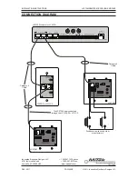
PAGE
2
DOC1309B
REV: 03-11
LC372M REMOTE MICROPHONE MODULE
INSTALLATION INSTRUCTIONS
CONNECTIONS
PIN 3
P
IN
4
P
IN
5
P
IN
6
G
N
D
+4
8V
N
O
S
H
U
N
T
=
6
dB
G
A
IN
50
d
B
26
d
B
J2
J1
3
1
2
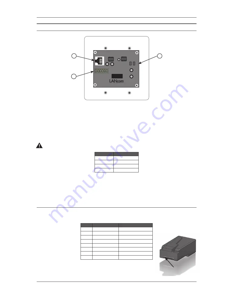
Figure 2 -
LC372M Rear View
1. Output RJ45 Connector
This connector is used to send the audio from the microphone and any third-party pushbutton call switches to an
LC372SR or LC331IC. See Table 2 for the connector wiring details.
2. Gain Selection Jumpers
These jumpers are used to adjust the microphone gain. Use higher gain settings when the microphone is not
picking up intercom calls in the room.
CAUTION –
Do not place shunts on both J1 and J2 at the same time. Doing so may result in damage to the
equipment.
Pin
Function
No Shunt
6 dB of gain
J1
26 dB of gain
J2
50 dB of gain
J1+J2
Not Allowed
Table 1 -
Gain Jumper Settings
3. Auxilliary Connector
This connector provides termination points when using pushbutton call switches from other manufacturers. A mo-
nentary switch can be wired to one of the four available control lines and ground. A voltage test point (+48VDC) is
provided as an aid in troubleshooting. Refer to Figure 3 for wiring instructions.
RJ45 Connector Wiring
Each unit connects to either an LC372SR Sound Reinforcement Module or LC331IC Integrated Communications Module
using CAT5 or better structured cable. Each connector should be wired as shown in Table 2.
Pin
Function
Cat5 Color Code
1
Audio +
Orange /W
2
Audio -
Orange
3
Switch out
Green /W
4
Switch out
Blue
5
Switch out
Blue/W
6
Switch out
Green
7
+48 VDC
Brown /W
8
Ground
Brown
Table 2 -
RJ45 Connector Wiring
PIN 1


