Cabinet Heater G*Y/D*Y Series
INSTALLATION, OPERATION, & MAINTENANCE MANUAL
23
11. ECM Fan Speed Adjustment, cont'd.
SECTION THREE – Controls Operation, Cont'd.
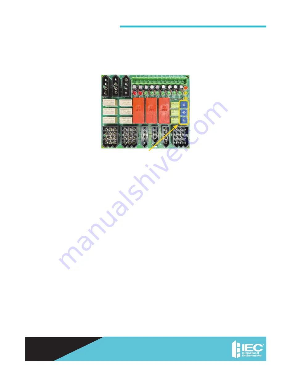
Potentiometers
Note:
The unit has been factory configured to produce PSC equivalent airflow on high speed, with medium and low
speed set at 80% and 60% of high, respectively. If these setting are acceptable, then no further configuring is required.
If alternative airflows are desired, use board mounted pots to adjust the airflow associated with each input.
To reset to initial factory settings, reference the voltages found on the sticker next to the pots.
Each output can be adjusted from 0 to 100% of the motor’s factory programmed operating range. Increasing the
voltage increases airflow, decreasing the voltage decreases airflow.
Adjusting the potentiometers requires the use of a Multi-meter capable of measuring 0~5 vdc.
1. Only trained and qualified individuals should attempt to adjust or service components on any electrical
component. Failure to follow safety rules could result in electrical shock or hazard.
2. 24 VAC power must be supplied to ECM board to make adjustments.
3. Set the electrical multimeter to Volts Direct Current (Vdc) on the 0~5 or 0~20 Vdc scale.
4. Attach to or probe the GND tab next to CN8 3-pin connector using the voltmeter black negative (-) lead)
5. Use red positive (+) lead to probe pins 10, 11 and 12 of the CN10 connector.
a. High speed: Probe pin 10 and adjust the H ADJ (CW for increasing speed, CCW for decreasing speed).
b. Medium speed: Probe pin 11 and adjust the M ADJ (CW for increasing, CCW for decreasing speed).
c. Low speed: Probe pin 12 and adjust the L ADJ (CW for increasing speed, CCW for decreasing speed).
Figure 22. 3-Speed, Potentiometer Adjustment (ECO V 2 Only)
(E025-71481108)


