background image

Assembly & Operation Manual 

24 


Table 3. Pulse control mode (the jumper is set on the J1 connector)


The turnstile 

operating 

modes


Actions 

to do


Indication


Turnstile status


on the RC


panel


on the LED display


Always locked 
(Locked for entry 
and exit)


Press the 

STOP


button on the 
RC panel 


The  red  indicator
above  the 

STOP

button is on 

The 

“Red


cross”

  for 

each passage 
direction and 

“Red 

line”

 pictograms are o 


The turnstile is locked 


Single passage in 
the set direction 
(open for


passage of one 
person in the 
chosen direction)


Press the 

LEFT

RIGHT 

button 

on the RC panel 

The green 
indicator above 
the button of the 
chosen 
passage 
direction 

«Left»

«Right» 

is on 


The 

“Green


arrow” 

and 

“Dyn

amic 

green” 

pictograms in the 
chosen passage 
direction are on 


When the passage is 
completed, the 
turnstile is locked 


Bi-directional 
single passage 
(open in both 
directions for


‘one

-by-one


passage)


Press both the 

LEFT 

and 

RIGHT 

buttons 

on the RC panel 
simultaneously 


The two green 
indicators 
(

«Left» 

and 

«Right»

) are on 

The 

“Green


arrow” 

for each passage 
direction and 

“Green 

line”

 pictograms are 

on. After the 
passage in the 
chosen direction the 

“Red


cross”

 is on for 

that direction. After 
the passage in both 
directions the 

“Red 

line”

 is on. 


The turnstile is locked 
in the direction of 
completed passage 


Free passage in 
the set direction 
(open for free 
passage in the 
chosen direction)


Press the 

STOP 

button and the 
button 
corresponding to 
the chosen 
passage 
direction 

LEFT

RIGHT 

simultaneously 


The green 
indicator above 
the button of the 
chosen 
passage 
direction 

«Left»

«Right» 

is on 


The 

“Green


arrow”

 in 

the chosen passage 
direction and 

“Green 

line”

 pictograms are 

on. 


Turnstile remains 
open in the set 
direction 

Free passage in 
the set direction 
and single 
passage in the 
opposite direction 
(open for free 
passage in the 
chosen direction 
and for passage


of one person in 
the opposite 
direction)


Set the 

Free 

passage in the 
set direction

” 

mode for one 
direction and 

Single passage 

in the set 

direction”


for the 

other. 


The two green 
indicators 
(

«Left» 

and 

«Right»

) are on. 


The 

“Green


arrow” 

for each passage 
direction and 

“Green 

line”

 pictograms are 

on. After the single 
passage the 

“Red 

cross”

 is on. 

After the passage in 
the free passage 
direction the turnstile 
remains open in both 
directions. After the 
passage in the single 
passage direction the 
turnstile remains open 
in the free passage 
direction but it gets 
locked in the single 
passage direction 


Always free (open 
for entry and exit)


Press all the 3 
buttons on the 
RC panel 
simultaneously: 

LEFT

STOP 

and 

RIGHT


The two green 
indicators 
(

«Left» 

and 

«Right»

) are on 


The 

“Green


arrow” 

for each passage 
direction and 

“Green 

line”

 pictograms are 

on. 


The turnstile remains 
open 

Summary of Contents for TTR-08

Page 1: ...Electromechanical Tripod Turnstile with Automatic Anti Panic Arms Assembly and Operation Manual TTR 08 ...

Page 2: ...ergency unblocking of the turnstile 15 5 11 Operation contingencies and response 15 6 MARKING AND PACKAGING 16 7 SAFETY REQUIREMENTS 16 7 1 Installation safety requirements 16 7 2 Operation safety requirements 16 8 INSTALLATION INSTRUCTIONS 17 8 1 Installation details 17 8 2 Installation tools 17 8 3 Length of cables 18 8 4 Installation procedure 18 9 OPERATION INSTRUCTIONS 23 9 1 Power up 23 9 2 ...

Page 3: ...and on the basis of maximum working load 30 persons min See Chapter 3 for information on the throughput capacity of the turnstile 2 OPERATION CONDITIONS The turnstile with regard to resistance to environmental exposure complies with GOST15150 69 category N1 for an outdoor application Operation of the turnstile is allowed at ambient air temperature from 20 C to 50 C up to 55 C under the shelter and...

Page 4: ...e passage mode 30 persons min Passage width 500 mm Arm rotation force max 3 kgf RC panel cable length 6 6 m1 Ingress Protection Rating IP54 EN 60529 Electric shock protection class III IEC 61140 Mean time to failure min 4 000 000 passages Mean lifetime 8 years Turnstile overall dimensions Fig 1 777 798 1084 mm Turnstile net weight max 37 kg Figure 1 Turnstile overall view 1 MAX allowed cable lengt...

Page 5: ... adhesive cable tie mount 3 Nylon cable tie 100 mm 5 Technical documentation Certificate 1 Assembly and operation manual 1 Package Box 1 4 2 Optional equipment supplied on request Turnstile power supply1 1 WRC kit2 1 Intrusion detector 1 Siren for alerts on unauthorized entry attempts 1 Anchor bolt SORMAT PFG IR 10 15 Finland 4 1 The power supply source must have load current min 6 A within 5 sec ...

Page 6: ...s of reset and quiet operation are ensured by a damper The optical arm rotation sensors are built into the turnstile housing to ensure accurate count of inputs to an ACS The turnstile is supplied with safe voltage maximum 14V Galvanic decoupling of the outputs ensures noise immunity of the turnstile electronics 5 2 Design The design of the turnstile is shown in Fig 2 Numbers in brackets correspond...

Page 7: ... hub 6 hub fastening bolts 7 LED indication side 8 AC power cable1 9 turnstile power supply1 10 emergency unblocking device Fire Alarm 1 11 turnstile power cable1 12 emergency unblocking device cable1 13 RC panel ACS controller1 WRC1 14 cable of RC WRC1 ACS controller1 15 anchor bolt1 16 plug 17 cover screws 1 Not included in standard delivery set ...

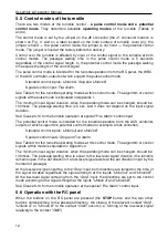
Page 8: ...s shown in Fig 3 There are three control buttons on the RC front panel intended for setting the turnstile operating modes The LED indicators are located above the buttons The middle button on the RC panel hereinafter the STOP button is intended to set the turnstile to the Always locked mode The left LEFT and the right RIGHT buttons are intended to unlock the turnstile for passage in the chosen dir...

Page 9: ...rnstile power supply XT4 Light A and XT5 Light B connector blocks to connect open closed remote indicators one indicator per each direction XT6 AntiPanic connector block to connect the electromagnet of automatic anti panic unblocking device J1 connector to select the turnstile control mode the jumper is fixed the pulse control mode the jumper is not fixed the potential control mode The jumper is f...

Page 10: ...optical arm rotation sensors and from the intrusion detector contact Detector and basing on those signals generates commands to the control mechanism and to the external devices indication on the RC PANEL Led A Led Stop and Led B the signal of hub turning in the corresponding direction PASS A and PASS B the signal of the turnstile ready for a current command Ready the alarm output signal Alarm and...

Page 11: ...he initial inactive state when the power is on the relay contacts PASS A PASS B Ready and Detector are closed voltage is supplied to the relay coil and the Alarm relay contacts are broken voltage is not supplied to the relay coil The CLB relay operation release is indicated by lighting up going down of the red test indicators located near the corresponding relays Fig 4 The output cascades for PASS...

Page 12: ...sec and it does not depend on the input signal duration See Clause 5 10 for the turnstile operation at special Fire Alarm control input The potential control mode is intended for the turnstile operation from the ACS controller outputs of which support the potential control mode for example a lock controller Standard control inputs Unlock A and Unlock B Special control inputs Stop and Fire Alarm Se...

Page 13: ...r arms reset to home position barrier arms turning at 112 the microcontroller removes the signal PASS A B contacting the PASS A B and Common takes place The Always free operating mode particularity in this mode the command described in step 5 is not generated and the set passage direction remains open 5 7 Operation with the WRC Control over the turnstile with the WRC is similar to that with the RC...

Page 14: ...t the signal from the intrusion detector comes it is also ignored The intrusion detector status signal is constantly transmitted to the Det Out and Common contacts of the CLB XT1 H connector block Fig 4 The emergency unblocking device is connected to the contacts Fire Alarm and GND of the out connector block XS1 that has contact leads with XT1 L connector block of the CLB in accordance with the co...

Page 15: ...ss passage delay for more than 30 sec one or both optical arm rotation sensors are out of order A special signal Ready is generated in each of the above cases In case of unauthorized access the Ready signal is formed as follows at 8 arm rotation one of the optical sensors Fig 14 responds and the output contacts Ready and Common get broken the beginning of the signal When the barrier arms reset to ...

Page 16: ...storage Transportation box dimensions L H W 1190 450 420 mm Transportation box weight gross no more than 53 kg 7 SAFETY REQUIREMENTS 7 1 Installation safety requirements The installation should be carried out only by the qualified personnel after careful study of this Manual Warning All the cables should be connected up when the power supply is switched off from the AC mains Only serviceable tools...

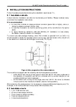
Page 17: ... it is recommended to create the passage area in such a way that the barrier arms should turn in the direction of movement at the angle no less than 70 Fig 9 Figure 9 Site preparation Recommendations The turnstile is equipped with the resetting device that operates as follows o at the barrier arm turning at the angle of more than 60 5 the reset is effected in the direction of movement and the turn...

Page 18: ...sulting from the turnstile incorrect installation and no claims from the Customer are accepted if the installation is made without following the instructions of the given Manual The turnstile connection layout is given in Fig 12 The CLB connectors location is shown in Fig 4 Cables parameters and their length are given in clause 8 3 The installation surface and passage area recommendations are give...

Page 19: ...rs installation place 8 Remove the back panel of the turnstile To do so move it up along the turnstile housing until it is unengaged from the housing The back panel is equipped with two pairs of engagement grips located on its upper and lower part Caution Fix the housing after laying the cables in the electric raceway and inside the turnstile housing Be careful and prevent the turnstile from falli...

Page 20: ...he cables in two points to the hole in the turnstile housing horizontal plane using hook and loop cable ties 17 Install the back panel in reversed order 18 Install the reinforcement plate on the turnstile in reversed order 19 Connect the indication board cable header to the S1 connection slot 20 Mount the cover with LED indication back into its place in the reverse order When the cover with LED in...

Page 21: ......

Page 22: ...upply 1 12V 6A A121 WRC kit 1 A131 Access control system 1 A141 Emergency unblocking device Fire Alarm 1 A15 11 A15 21 Remote indicators 2 RI A RI B A161 Remote indicator power supply 1 A171 Siren 1 12VDC A181 Intrusion detector 1 XS1 Connector block 24 contacts 1 PSK1 12 12 Klemmsan 2 S1 A2 cover connection slot 1 1 Power cable 1 2 Control cable 1 3 CLB indication cable 1 4 Turnstile cover indica...

Page 23: ... accordingly After the power up wait until the moment of the test indicator inside the intrusion detector going off from 10 to 50 sec Put your hand before the intrusion detector The continuous signal will sound when the intrusion detector activates To eliminate that sound signal press any button on the RC panel The sound will stop without pressing the button in 5 sec The turnstile is ready for ope...

Page 24: ...the direction of completed passage Free passage in the set direction open for free passage in the chosen direction Press the STOP button and the button corresponding to the chosen passage direction LEFT RIGHT simultaneously The green indicator above the button of the chosen passage direction Left Right is on The Green arrow in the chosen passage direction and Green line pictograms are on Turnstile...

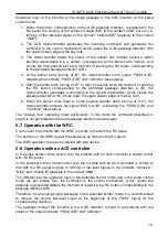
Page 25: ...contacts Unlock A Unlock B and Stop of the XT1 L connector block relatively to the contact GND 9 3 Operating modes of the turnstile at potential control mode See Table 4 for the operating modes set from the RC panel Setting the operating modes for each direction is independent i e setting the operating mode for one direction does not change the operating mode set earlier for the opposite one If by...

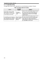
Page 26: ... the AC mains open the turnstile housing cover Check the power cable serviceability and reliability of its connection to the CLB XT3 connector block The turnstile is not controlled in one of the directions and there is light indication on the turnstile housing and on the RC panel The CLB does not receive a control signal for this direction Switch off the turnstile power supply from the AC mains op...

Page 27: ...springs and roller the arm rotation sensors and the damper Fig 14 Caution Avoid the ingress of lubricant on the arm rotation sensor disc and the roller surfaces 8 Remove dust from the arm rotation sensor disc located in the spacing of the arm rotation optical sensors with alcohol gasoline blend applied with a cloth Avoid the ingress of dust on the operational spacing of the both arm rotation optic...

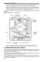
Page 28: ...nical Support Department the IDTRONIC TSD Figure 14 Location of the interior components of the turnstile mechanism 11 TRANSPORTATION AND STORAGE The turnstile in the original package should be transported in closed freight containers or in other closed type cargo transport units During storage and transportation the boxes can be stacked no more than 4 layers high The storage of the turnstile is al...

Page 29: ... in the direction B open for passage of one person in the direction B Active front is at the contact Unlock B while there is a high level at the contacts Stop and Unlock A At this command the passage direction B opens either for 5 sec or until the passage has been effected in this direction or until the command Always locked and the status of the passage direction A does not change The command is ...

Page 30: ...passage direction B opens until the command Always locked is received the status of the passage direction A does not change at that Free passage open for free passage in both directions Active front is at the contact Unlock A while there is a low level at the contacts Unlock B and Stop or active front is at the contact Unlock B while there is a low level at the contacts Unlock A and Stop or active...

Page 31: ...lock B At this command the direction A opens up to the low level signal removal from the contact A or until the command Both directions locked is received The status of the direction B does not change at that The direction B is open open for passage in the direction B There is a low level at the contact Unlock B while there is a high level at the contacts Stop and Unlock A At this command the dire...

Page 32: ......

Reviews: