background image


                                                                          6                                                     


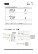
7. Wire Color Table of the Reader 


8. Wire Connection to Access Controller 


SIGNAL 

COLOR 

Main Power (+12V) 

Red 

Power Ground (GND) 

Black 

ABA Track II CP Out 

Orange 

Wiegand Data 0 Out / 

ABA Track II Data Out 

Green 

Wiegand Data 1 Out / 

ABA Track II Clock Out 

White 

Buzzer Control In 

Blue 

LED Control In 

Yellow 

RS232 (TX) 

Purple 

Not Connect 

Brown 

Not Connect 

Gray 

* Please cut out tail connector before installation. 

Summary of Contents for Star RF30

Page 1: ...User s Manual Proximity Card Reader...

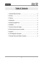
Page 2: ...eral 3 3 Features 4 4 Specification 4 5 Identifying Supplied Parts 5 6 Installation 5 7 Wire Color Table of the Reader 6 8 Wire Connection to Access Controller 6 9 Operation 7 10 FCC Registration Info...

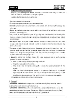
Page 3: ...to qualified service whenever service or repair is required Opening or removing the covers may expose you to dangerous voltages or other risks Also incorrect reassembly can cause electric shock when t...

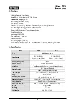
Page 4: ...Third Party Controllers 4 Specification Model RF30 IP30 CPU 8bit Microprocessor Read Range IDC170 IDC80 Up to 12 inches 30cm IPC80 IPC170 Up to 12 inches 30cm Reading Time Card 30ms Power Current DC1...

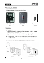
Page 5: ...3 3 8 38cm apart in vertical and drill one 1 2 hole for the reader cable 1 7 4 31cm apart from the top hole If you have installed an electric gang box then skip this step and go to step 4 2 6 2 Put r...

Page 6: ...12V Red Power Ground GND Black ABA Track II CP Out Orange Wiegand Data 0 Out ABA Track II Data Out Green Wiegand Data 1 Out ABA Track II Clock Out White Buzzer Control In Blue LED Control In Yellow RS...

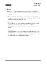
Page 7: ...t reading 9 3 LED Control To change the LED colors you may connect the LED Control Input Yellow wire to ground and the Green LED will turn on indicating that the reader is in standby mode Present prox...

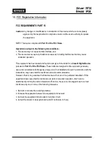
Page 8: ...nt to Part 15 of the FCC Rules These limits are designed to this equipment generates uses and can radiate radio frequency energy and if not installed and used in accordance with the instructions may c...

Page 9: ...property is located where this product will be used it would be extremely difficult to determine the actual damages that may result from a failure of the product to perform as anticipated and the low...

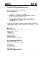
Page 10: ...ter Product without RMA Code is not accepted If you have any questions or problems regarding the RMA services please contact us using the contact information below Friendly representatives at IDTECK a...

Page 11: ...11 MEMO...

Page 12: ...HE2X The specifications contained in this manual are subject to change without notice at any time 5F Ace Techno Tower B D 684 1 Deungchon Dong Gangseo Gu Seoul 157 030 Korea Tel 82 2 2659 0055 Fax 82...

Reviews: