background image

Safety Information

1

p.1

CAUTION

: TO REDUCE THE RISK OF ELECTRIC SHOCK, DO NOT REMOVE COVER

(OR BACK) NO USER SERVICEABLE PARTS INSIDE. REFER SERVICING TO QUALIFIE

D SERVICE PERSONNEL.

This symbol indicates that dangerous voltage consisting a risk of electric shock is pres

ent within this unit.

This exclamation point symbol is intended to alert the user to the presence of importa

nt operating and maintenance (servicing) instructions in the literature accompanying the ap

pliance.

WARNING

To reduce the risk of fire or electric shock, do not expose this appliance to rain or moisture.

WARNING

1.

Be sure to use only the standard adapter that is specified in the specification sheet. Usin

g any other adapter could cause fire, electrical shock, or damage to the product.

2.

Incorrectly connecting the power supply or replacing battery may cause explosion, fire,

electric shock, or damage to the product.

Summary of Contents for ipass IP10

Page 1: ......

Page 2: ...Y INSTRUCTIONS 2 General 3 Features 4 Identifying Supplied Parts 5 Specification 6 Check Points and Tip 7 Installation 8 Wire Color Table of the Reader 9 Wire Connection to Controller 10 Operation 11 FCC REGISTRATION INFORMATION 12 RMA Request ii 1 3 4 5 6 7 8 10 11 12 13 14 15 ...

Page 3: ...he user to the presence of importa nt operating and maintenance servicing instructions in the literature accompanying the ap pliance WARNING To reduce the risk of fire or electric shock do not expose this appliance to rain or moisture WARNING 1 Be sure to use only the standard adapter that is specified in the specification sheet Usin g any other adapter could cause fire electrical shock or damage ...

Page 4: ...t in any way SAMSUNG is not liable for problems caused by unauthorized modifications or attempted repair 10 When cleaning do not spray water directly onto parts of the product Doing so may ca use fire or electric shock CAUTION 1 Do not drop objects on the product or apply strong blows to it Keep away from a locat ion subject to excessive vibration or magnetic interference 2 Do not install in a loc...

Page 5: ...u r safety If the provided plug does not fit into your outlet consult an electrician for repla cement of the obsolete outlet 10 Protect the power cord from being walked on or pinched particularly at plugs convenie nce receptacles and the point where they exit from the apparatus 11 Only use attachments accessories specified by the manufacturer 12 Use only with cart stand tripod bracket or table spe...

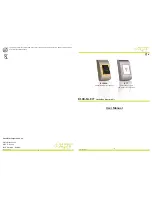
Page 6: ... IP10 20 is an elegant looking proximity reader It can be easily mounted to metal door frame mullion or any flat wall surface The iPASS IP10 20 is a credible product with e poxy potting that enables you to install it outside ...

Page 7: ...ilable Output Format 26bit Wiegand Default RS232 Optional Simultaneous output of 26b it Wiegand and RS232 Easy to Install on Metal Door Frame or Mullion IP10 and Wall Mount IP20 Suitable External LED Control and External Buzzer Control Solid Epoxy Potted Waterproof IP65 IP66 Reverse Polarity Protection ...

Page 8: ...Identifying Supplied Parts 4 p 6 Please unpack and check the contents of the box ...

Page 9: ... Wiegand Default RS232 Optional LED Indicator 2 Color LED Red and Green Beeper Piezo Buzzer Operating Temperature 35 to 65C 31 to 149F Operating Humidity 10 to 90 relative humidity non condensing Color Material Dark Pearl Gray Polycarbonate Dimension W x H x T 46mm x 122mm x 23mm 1 82 x 4 81 x 0 87 76mm x 124mm x 23 5mm 3 x 4 89 x 0 87 Weight 160g 0 35lbs 185g 0 41lbs Warranty Life time Index of P...

Page 10: ...distance assume to using DC resistance of cable of 100Ω 100m and the reader power is supplied from the ACU the voltage drop of the GND wire will be 1V In this case the Wiegand data signal cannot be measured lower than 1V The most of ACU is capturing the signal by the voltage level of data input and 1V is the critical point whether the ACU read the data logic 1 or logic 0 therefore the reader o utp...

Page 11: ...ngle wire Use separate power for the reader Disconnect 12V wire from the ACU and conne ct external power supply to the reader nearby then there will be no current flow thr ough the GND wire and no voltage drop between both ends of GND wire ...

Page 12: ...p hole Skip this step if you have installed an electric gang box 2 Put reader cable into the center hole and install the reader module by using two 6 32 o r M3 screws Not included 3 Put bezel on to the reader module Then push bezel until you hear the locking sound 4 To detach the bezel hold both sides of the bezel push the bezel to the bottom and pu ll the bezel forward ...

Page 13: ...Wire Color Table of the Reader 8 p 11 ...

Page 14: ...Wire Connection to Controller 9 p 12 ...

Page 15: ... LED Control To change the LED colors you may connect the LED Control Input Yellow wire to pow er ground The green LED is indicating that the reader is in standby mode Present proximity card The LED changes the color to red simultaneously then to green again for the next reading 4 Buzzer Control When the reader reads the proximity card one beep sound generates in normal operati on mode but you can...

Page 16: ...e received including interference that may caus e undesired operation This equipment has been tested and found to comply with the limits for a Class A Digital De vice pursuant to Part 15 of the FCC rules These limits are designed to this equipment gener ates uses and can radiate radio frequency energy and if not installed and used in accordan ce with the instructions may cause harmful interference...

Page 17: ...g Gangseo Gu Seoul 157 030 Korea Tel 82 2 2659 0055 Fax 82 2 2659 0086 E mail webmaster idteck com Website www idteck com E Training Center http www idtecktraining com IDTECK Production Facility and RMA Center 2F 89 4Dodang Dong Weonmi Gu Bucheon Si Gyeonggi Do 420 130 Korea Tel 82 2 2659 0055 Fax 82 2 2659 0086 E mail webmaster idteck com Website www idteck com E Training Center http www idtecktr...

Reviews: