9. Resets, Clocks and Power-up Options
168
PowerSpan II User Manual
80A1010_MA001_09
Integrated Device Technology
www.idt.com
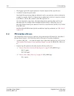
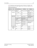
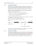
The relationship between the reset and direction control pins is defined in
.
The dedicated direction control pins must either be pulled up or down. At least one of the bidirectional
reset pins must be configured as an input. Typically, the bus reset pin on the bus closest to the system
host must be configured as an input.
9.1.1.2
Reset Response
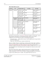
The assertion of an external reset pin elicits a specific response from PowerSpan II.
defines
how various PowerSpan II resources are affected by active reset pins.
Table 43: Reset Direction Control Pins
Control Pin
Associated Reset Pin
Description
PB_RST_DIR
PB_RST_
Direction of PB_RST_
• When PB_RST_DIR = 0, PB_RST_ is an
input
• When PB_RST_DIR = 1, PB_RST_ is an
output
P1_RST_DIR
P1_RST#
Direction of P1_RST#
• When P1_RST_DIR = 0, P1_RST# is an
input
• When P1_RST_DIR = 1, P1_RST# is an
output
P2_RST_DIR
P2_RST#
Direction of P2_RST#
• When P2_RST_DIR = 0, P1_RST# is an
input
• When P2_RST_DIR = 1, P2_RST# is an
output
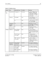
Table 44: PowerSpan II Reset Response
Reset Pin
PowerSpan II Resource
PLLs
PCI-1
Registers
PCI-2
Registers
PB
Registers
PowerSpan II
Device
Specific
Registers
Finite State
Machines
PO_RST_ = 0
Yes
Yes
Yes
Yes
Yes
Yes
HEALTHY# = 1
Yes
Yes
Yes
Yes
Yes
Yes
PB_RST_ = 0
No
No
No
Yes
Yes
Yes
P1_RST
#
= 0
No
Yes
No
No
Yes
Yes
P2_RST
#
= 0
No
No
Yes
No
Yes
Yes

