P9038 LAYOUT GUIDE
10
08/23/15
AN-894
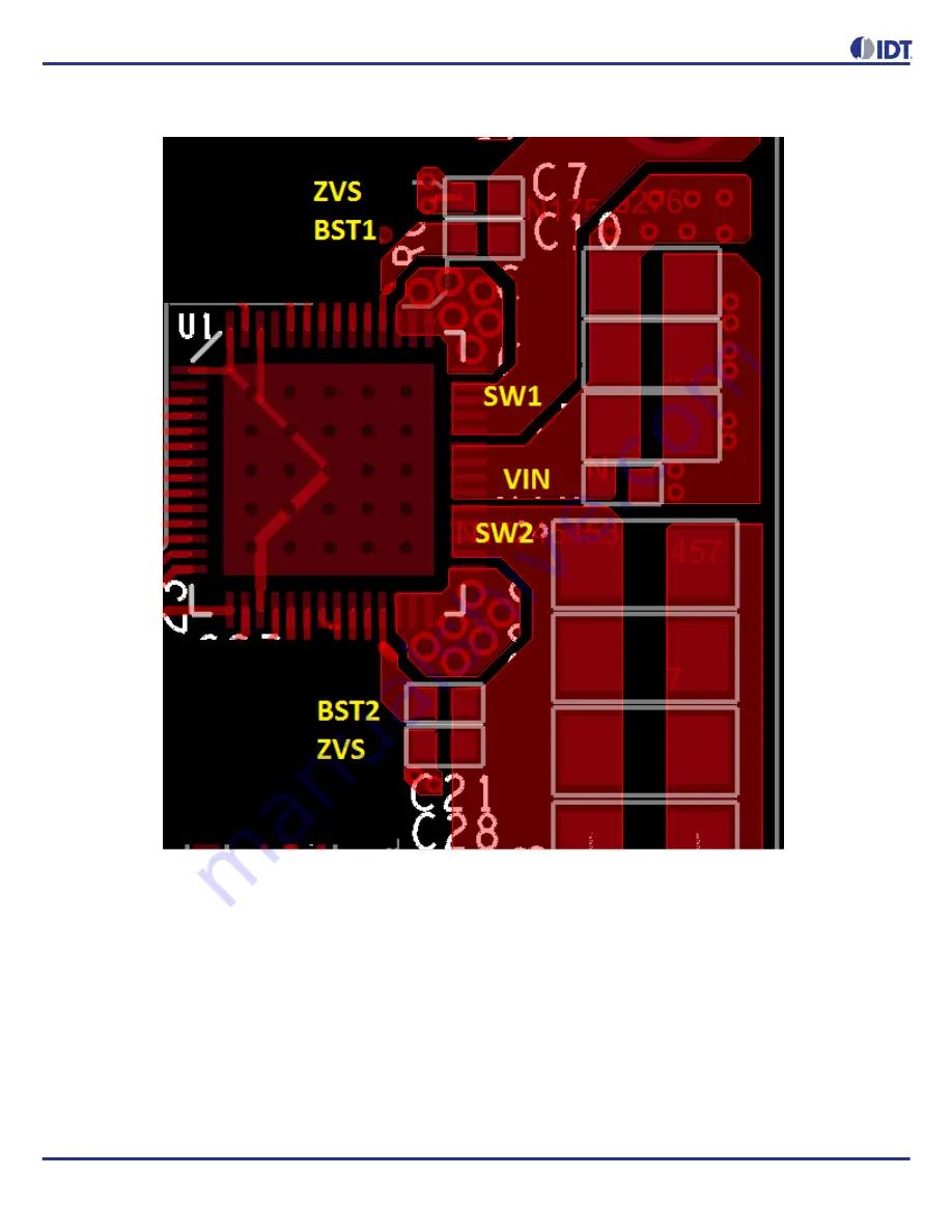
Figure 8. Image of BST1, BST2 and ZVS Components for P9038 QFN (VFQFPN) Layout
Next, the current sense resistor and the associated filters are crucial for Foreign Object Detection (FOD) accuracy, as they
impact the input power calculations. The P9038 calculates the input power using the voltage on the IN pins and the current
detected as a voltage drop across the sense resistor (R2). Since the signal sensed across this resistor will be 20 mV or below,
signal integrity is important for proper operation. Best practice will follow the guidance in the following image and the length of
these connections will be minimized. The current sense resistor should be placed in close proximity to the P9038 device for best
results. Notice how the voltage drop (+,-) across R2 is Kelvin sensed by filter resistors R3 and R4. This is done to improve
accuracy of the input current measurements needed for FOD. The GND connection for C4 and C3 should be located on the
EPAD GND side of the GND slot.


