background image

40

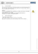
9 - MAINTENANCE

WARNING!

EVERY TIME THE MACHINE IS CLEANED OR MAINTAINED IT MUST FIRST BE STOPPED BY 

FOLLOWING THE STEPS DESCRIBED IN PARAGRAPH 8.4.

TO GUARANTEE MACHINE SAFETY, YOU ARE ADVISED TO USE ONLY SPARE PARTS AUTHORI-

ZED BY THE MANUFACTURER. DO NOT CARRY OUT TEMPORARY OR DANGEROUS REPAIRS.

CAUTION!

DURING OPERATION, THE SYSTEM MUST MAINTAIN A NOISE LEVEL THAT COMPLIES WITH 

LEGISLATION. FURTHERMORE, THERE MUST BE NO WATER LEAKAGE FROM THE PUMPING 

MODULE OR THE LINE.

9.1 MAINTENANCE
MACHINES contain a high pressure water supply, an electric motion system and a control 

system that need a big maintenance. Everything works, most of the time, in awful climatic 

conditions: bad weather, humidity, ice, hot, hard and non-stop usage and, not always 

adequate water, not always strained fuel.

The solution is preventing breakages. How to do it? 

Simply replacing the components before they cause breakages.

9.2  

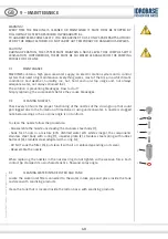
CLEANING NOZZLES

Check every 50 hours the proper functioning of the nozzles of the crown group that could 

get clogged due to the formation of limestone or using unclean water.  A nozzle is clogged 

note because drips or has a spray angle is not uniform. 

To clean the nozzle follow the procedure:
- Disassemble the nozzle unscrewing the stainless steel body (1);
- Soak for 4 hours in a mixture, 80% distilled water 20% white vinegar, the components 

stainless steel body with o-ring (1), impeller plate (2), stainless steel spring with rubber 

ball seal (3), stainless steel adapter with o-ring (4);
- DO NOT soak the filter (5), but clean it with air or replace depending on its wear;
- Reassemble the nozzle.

When replacing the nozzles in the nozzles ring do not tighten with excessive force. Each 

contact tip stamped its own characteristics, flow and spray angle.

9.3  

CLEANING WATER INTAKE FILTER AND TANK

Locate the water inlet filter connected to the water intake pipe and place inside the tank 

and clean with sanitizing products.

Clean the tank that is located inside the rattan base, with sanitizing products.

GB

1

2

5

3

4

1

4

Cop

yright ©2017 Idr

obase Gr

oup

. All rights r

eserv

ed

.

Summary of Contents for AURORA

Page 1: ...cchina e deve obbligatoriamente essere conservato per futuri riferimenti fino alla demolizione della macchina IMPORTANT Before installing and using the machine im perative that the in staller and the...

Page 2: ...e or durability of the machine and create the potential risk to the machine itself or the staff as well as make void the warranty The descriptions and illustrations contained in this publication are n...

Page 3: ...31 5 2 TOWER PACK 31 5 3 BASE PACK 31 6 ASSEMBLY AND INSTALLATION 32 7 OPERATION AND USE 7 1 ELECTRICAL CONTROLS 35 7 2 RANGE APPLICATIONS 36 7 3 WORKING LIMITS 36 7 4 EATER CONNCTION TO THE MACHINE...

Page 4: ...follow the safety regulations to the country of installation in addition to the rules dictated by common sense You should not use the machine if you note any defects or damages that could compro mise...

Page 5: ...OUP SRL 2 2 MACHINE IDENTIFICATION The machine is distinguished by a manufacturer s plate 2 3 WARRANTY All of our equipments are subjected to accurate and rigorous tests and are covered under warranty...

Page 6: ...OT LIABLE The manufacturer is not liable for damage caused by the following Improper use of the machine or use by untrained people Use of non genuine spare parts Non compliance with maintenance Unauth...

Page 7: ...both installation and storage During the handling of the machine on sloping surfaces potholes or on particularly un stable ground there is a risk that the machine chutes The movement of the machine u...

Page 8: ...HED ON ALWAYS DISCONNECT FROM THE ELECTRICAL SUPPLY BEFORE CARRYING OUT REPAIRS OR REMOVING THE COVER WARNING AVOID STORING OR USING THE MACHINE IN EXTREME TEMPERATURES FROST MAY CAUSE SERIOUS DAMAGE...

Page 9: ...o Gazebo Through the use of suitable optional kits or models for each of these types achieves maximum performance 3 2 COMPOSITION The main components of the machine are 3 PRODUCT PRESENTATION GB 4 12...

Page 10: ...r 6 Max Load Table Top 5 kg 11 lb Frequency 50 Hz Water Tank 10 L 2 64 US gal Absorption 0 8 A Max Pressure 25 bar 362 6 psi Noisiness 51 Db Power 120 W 0 16 HP Flow rate 18 L h 0 079 USGpm INFORMATIO...

Page 11: ...ng all of the requested accessories 5 2 TOWER PACK Rattan tower with fan electric and hydraulic connection Table N 2 semitables with centering pins Kit of screws for fan cover assembly Kit of screws f...

Page 12: ...LATION GB AFTER UNPACKED PROCEDE WITH 1 OPEN THE DOOR OF THE RATTAN BASE GET OUT TANK AND CONNECT WATER PIPE ELECTRIC CABLE REPLACE TANK AND CLOSE THE DOOR OF THE RATTAN BASE Copyright 2017 Idrobase G...

Page 13: ...THE WATER CONNECTIONS TUBE WHITE AND ELECTRICAL BLACK CORD H2O 4 FIX THE TOWER TO THE BASE TIGHTENING THE HEX SOCKET BUTTON HEAD CAP SCREWS M6X35 2 FIX FAN COVER AND FAN COVER SUPPORT TO THE FAN WITH...

Page 14: ...TO THE RATTAN TOWER 8 FIX SEMI TABLES TIGHTENING THE HEX SOCKET BUTTON HEAD CAP SCREWS M6X15 9 SCREW IN NOZZLES THE INSTALLER MUST SECURELY TO THE FLOOR GROUND THE MACHINE WITH AT LEAST 3 SCREWS OF T...

Page 15: ...y the LED continuous light shutdown is signaled by LED flashing light BLOCK PUMP If during operation of the pump there is no pressure in the line tank empty or broken hydraulic hose the pump stops Thi...

Page 16: ...till closed dimensioned accor ding to the flow and pressure to which the system should work The pipes laid shall not have any bending Serial connection to the water supply is carried out by a female f...

Page 17: ...DESTRUCTION OF THE MACHINE MUST BE CARRIED OUT ONLY BY A TRAINED PERSON OR BY A QUALIFIED TECHNICIAN When it has been decided to destroy the machine and render it unusable it is recom mended that all...

Page 18: ...every 50 hours the proper functioning of the nozzles of the crown group that could get clogged due to the formation of limestone or using unclean water A nozzle is clogged note because drips or has a...

Page 19: ...IT IS GOOD TO REMEMBER THAT THE MAINTENANCE CARRIED OUT PROPERLY CAN MINIMI ZE THE DOWNTIME DUE TO FAILURE A REPAIR DONE IN A TIMELY MANNER TO AVOID FURTHER DETERIORATION USE AS MUCH AS POSSIBLE ORIGI...

Page 20: ...that all parts which could be dangerous are rendered safe removing all of the electrical components while conforming to current legislation regarding the scrapping of these materials The various comp...

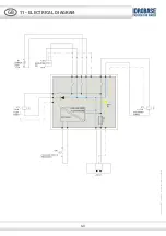
Page 21: ...43 11 ELECTRICAL DIAGRAM GB Copyright 2017 Idrobase Group All rights reserved...

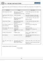
Page 22: ...Faulty fan Connect the plug to the power outlet Call Service The machine vibrates a lot and or is noisy Water level in the tank insufficient Faulty pump Fill the tank with drinking water Call Service...

Page 23: ...45 NOTE GB Copyright 2017 Idrobase Group All rights reserved...

Page 24: ...46 NOTE GB Copyright 2017 Idrobase Group All rights reserved...

Page 25: ...47 NOTE GB Copyright 2017 Idrobase Group All rights reserved...

Page 26: ...montaggio messa in funzione manutenzione preventiva installation start up preventive maintenance www idrobase com www idrotech com www sparesclub com www enjoyyourfurniture com Copyright 2017 Idrobase...

Reviews: