background image


2014-03-24 

182 

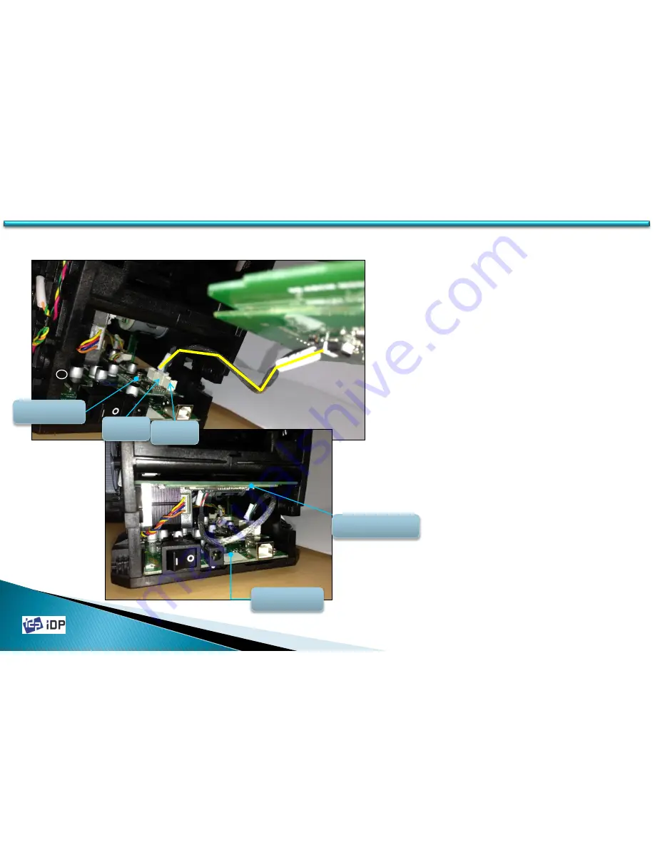
1. Wire of Contactless Encoder is located on  

the upper side of USB Hub on Printer 

Main Board. Connect the wire of 

Contactless Encoder to USB port (

Orange Line

). 

2. At this time, the wire of Contactless 

Encoder must be connected to 

PORT2

 or 

PORT3

.


CONTACTLESS ENCODER Option Wiring 

 C.4 Internal RF Option 

PCBA USB 

HUB 

PCBA INTERNAL 

RF OPTION PART 

M / B 

182 

PORT 2 

PORT 3 

* For assembling USB HUB on 

Printer Main Board, refer to C.5. 

* For assembling ETHERNET 

Option, refer to C.6 

Summary of Contents for Smart-30

Page 1: ...2014 03 24 Color ID Card Printer Technical Manual...

Page 2: ...information contained herein may be subject to modification without prior notice IDP Corporation accepts no liability for any possible errors herein nor for any accidental damage or damage caused thr...

Page 3: ...atures 1 1 3 Ribbon Cartridge Feature 1 1 4 LED Status and Button Operation 1 2 Printer Installation and Instructions 1 2 1 Ribbon Installation 1 2 2 Card Thickness Adjustment 1 2 3 Cards Load 1 3 Pri...

Page 4: ...Side Cover Right Left 3 1 2 LED Button Unit 3 1 3 Stacker Unit 3 1 4 Front Cover 3 1 5 Rear Cover 3 2 Top Cover Unit 3 2 1 Thermal Print Head 3 2 2 Top Cover 3 2 3 Cooling Fan 3 2 4 Top Cover Frame 3...

Page 5: ...llers 3 5 1 Cleaning Roller Cleaning Roller Fixed 4 Administration 4 1 Setup 4 1 1 Overview 4 1 1 1 Function 4 1 1 2 Start 4 1 2 Printer Setup 4 1 2 1 Basic Setup 4 1 2 2 Expansion Setup 4 1 3 Printer...

Page 6: ...t 4 1 3 7 Security 4 1 3 8 Etc 4 2 Test 4 2 1 Overview 4 2 2 Basic Operation 4 2 2 1 Select 4 2 2 2 Control 4 2 2 3 Print 4 2 2 4 Allocation 4 2 2 5 Status 4 2 2 6 Message 4 2 3 Encoding 4 2 3 1 Magne...

Page 7: ...4 2 4 1 Printer Status Code 4 2 4 2 Printer Error Code 4 3 Firmware 4 3 1 Overview 4 3 2 Automatic Update 4 3 3 Manual Update 5 Trouble Shooting 6 Appendix A Service Parts List B Expanded View C Opti...

Page 8: ...inter working status can be seen by LED and most of the operations can be controlled by buttons The following shows the external functional features found on your Smart Printer 1 1 Printer Basic Infor...

Page 9: ...n REAR CARD OUTLET Eject Error Card POWER SWITCH Printer On Off DC POWER CONNECTOR Connect DC power Adapter USB PORT Communicate with PC using USB cable ETHERNET PORT OPTION Use it after removing the...

Page 10: ...HOPPER Load new cards for printing and encoding CARD THICKNESS CONTROL BRACKET Loosen screws and adjust bracket according to card thickness RIBBON CARTRIDGE Install ribbon and cleaning roller THERMAL...

Page 11: ...it is broken or damaged In this case please contact printer reseller Ribbon Take Up Core Collect the ribbon used in printing Ribbon Supply Core Provide the ribbon for printing Disposable Cleaning Roll...

Page 12: ...1 1 4 LED Status and Button Operation SMART 30 Printer shows the real time working status to user using LED and can be controlled by button according to each working status BUTTON LED 1 1 Printer Basi...

Page 13: ...hysical Key option and SMART 30 is locked by the key or activating Root User authentication option and SMART is locked by the password Printer is locked so can t be operated 4 S m a r t Verify your PC...

Page 14: ...RT 30 search ribbon again 10 Check Please TPH Not Found RED Blink Thermal Print Head is not installed When the thermal Print Heat is not installed or disconnected to head cable this message is display...

Page 15: ...e RF Error 21 Printing Data Error 06 Card Move Error from Printer to Flipper 22 Card Back Out Error 07 Card Move Error from Flipper to Printer 23 Magnetic Data Removing Error 08 Thermal Print Head Up...

Page 16: ...section we invite you to know the proper method to install the ribbon and the cleaning roller into the printer 1 2 Printer Installation and Instructions Fig 2 1 Open Top Cover Fig 2 2 Take out ribbon...

Page 17: ...press the opposite no 2 until it clicks Insert the take up side of the ribbon to no 3 and no 4 by the same way And fasten the ribbon Caution If the ribbon is not fastened a rolling up error might hap...

Page 18: ...cleaning roller Fig 2 6 Peel the protective wrapper 7 Peel the protective wrapper from the cleaning roller To avoid contamination always hold the cleaning roller Be careful to touching dust and contam...

Page 19: ...Cover 1 2 Printer Installation and Instructions 8 Install the ribbon cartridge to the printer after install the ribbon and cleaning roller to the cartridge 9 Close the top cover until it clicks If it...

Page 20: ...ss several cards may be taken into printer at the same time and error occur Fig 2 9 Card Thickness Adjustment 1 Card Thickness Adjustment HOPPER GATE 3 For Adjusting card thickness please loosen two s...

Page 21: ...with significant adhesive force These cards must be physically separated from each other before inserted into the feeder If not separated feeding or printing problems may occur Fig 2 14 Prepare cards...

Page 22: ...e hopper Please push a card until you can t push it any more Fig 2 18 Cards Load 3 Fig 2 19 Cards Load 4 3 Restore the cards stack to its original condition 4 Place the cards to the hopper and close t...

Page 23: ...n Capacity Color YMCKO 250 cards roll Color YMCKOK 200 cards roll Black Overlay KO 600 cards roll Mono 1200 cards roll Black Gold Silver Hopper Stacker Hopper 100 cards Stacker 25 cards Interface USB...

Page 24: ...2014 03 24 24 24 2 1 Sensors 2 1 Sensors CASE OPEN SENSOR COLOR IN SENSOR CARD IN SENSOR ENCODER SENSOR HEAD UP DOWN SENSOR COLOR OUT SENSOR CARD OUT SENSOR...

Page 25: ...2014 03 24 25 25 2 2 Thermal Head and Rollers 2 2 Thermal Head and Rollers Cleaning Roller Fixed Cleaning Roller Card Supply Roller MS Roller Thermal Head IC Roller Printing Roller Card In Roller...

Page 26: ...2014 03 24 26 26 2 3 Motors 2 3 Motors Main Driver Step Motor Ribbon Driver Motor DC FAN Head Up_Down Hopper Motor DC...

Page 27: ...2014 03 24 27 27 2 4 PCBs 2 4 PCBs Front Display PCB Main Ribbon RF...

Page 28: ...2014 03 24 28 2 5 Wired Diagram 2 5 Wired Diagram...

Page 29: ...n Bottom Frame 2 Open Front Cover and Top Cover 3 Grip the bottom part of right left Side Cover and pivot from upper part of right left Side Cover 4 Upper part of right left Side Cover is connected wi...

Page 30: ...n Frame using screw driver and then Hook is disassembled At this time pull carefully the LED Button unit to disassemble it 3 When pull out LED Button unit be cautious not to make damage on the wire of...

Page 31: ...er 2 Pull out Stacker to separate it from printer At this time hold printer to prevent printer from moving 3 When install Stacker into printer push it according the rail of the Stacker and the track o...

Page 32: ...4 03 24 3 1 4 Front Cover 1 Open the Front Cover 2 Broaden the gab between Main Frame and Front Cover using screw driver and disassemble Front Cover from Main Frame Front Cover Front Cover 32 3 1 Cove...

Page 33: ...2014 03 24 3 1 5 Rear Cover 1 Rear Cover is assembled to Main Frame by Hook 2 Unlocked the Hook on both side of the Rear Cover using Screw Driver Left View Right View 33 3 1 Covers Rear Cover...

Page 34: ...l Print Head is fixed by Hinge and Hook on Top Cover Frame 3 Press the push button of Hook rotate the thermal print head to the bottom side and disassemble thermal print head from Top Cover Frame 4 Di...

Page 35: ...2 Top Cover 1 Top Cover is fixed to Top Cover Frame by 3 screws and 2 Hooks 2 Loosen Screws and unlock Hooks using screw driver and then disassemble Top Cover from Top Cover Frame Screw 35 3 2 Top Co...

Page 36: ...g Fan 3 Fan Wire is connected to Connector of Main Board through inside of Printer 4 Disassemble Bottom Frame from Printer and disconnect Fan Wire from Connector 5 Arrange Fan Wire and disconnect Be c...

Page 37: ...nsor Wire on Thermal Print Head position 4 Loosen 2 screws and broaden both Main Frames and then disassemble Top Cover Frame 5 To disassemble Color in Sensor push Snap for fixing and pull out Color In...

Page 38: ...1 1 3 2 Hooks are at same position on each side Lift and Right on Bottom Frame 4 To unlock Hooke push Main Frame to the right and push Bottom Frame to the left 5 More easy way to unlock Hooks hold Ma...

Page 39: ...ous not to make damage on T4 FFC 2 T5 Wire is connected to LCD Button unit On 3 1 2 when disassembling LCD Button unit T5 was disconnected form LCD Button unit but disconnect T5 Wire to disassemble Ma...

Page 40: ...FFC Wire from PCB Ribbon RF Be cautious no to make damage on FFC connector 3 Lift Hook parts by using the screw driver or other device and pull out paralleled to Side Frame direction to disassemble 3...

Page 41: ...Belt 3 and GEAR 7 and then can loosen 3 screws for fixing Step Motor 3 Step Motor is located inside of Frame 4 When assemble Step Motor adjusting the tension by assembling Pulley 2 and Time Belt 3 to...

Page 42: ...ension Setting After put the belt to the pulley press the pulley as 1 5 2 kgf to the No 1 arrow direction as Fig 3 1 In this state tighten 3 screws to set tension and fix Step Motor 3 4 2 BELT Tension...

Page 43: ...s assembled to Ribbon Motor enable to disassemble Ribbon Motor 4 Head Up Down Motor is fixed by 3 screws inside of Frame See B 2 1 ASSY S3 LEFT 1 B2 2 ASSY S3 LEFT 2 5 After disassembling Gear 25 and...

Page 44: ...isassemble E Ring on the end of Roller 3 Disassemble Bearing or Bushing fixed on Frame While pushing Roller to Frame Right Side Disassemble Left Side of Roller from Frame 3 5 Rollers 3 6 Rollers Clean...

Page 45: ...ge 3 Transform the fixing parts of Main Frame for Hinge and disassemble Cleaning Bracket 4 Disassemble Bush on the end of Cleaning Roller Fixed 5 While pushing Cleaning Roller Fixed to the Right Side...

Page 46: ...Ribbon Color Sensor Recognition Set the sensor value to distinguish the ribbon color Security Set the value for the printer security Etc Set the printer s hardware version and the printer state 4 1 S...

Page 47: ...be shown and can change that value The password is saved to SMART Card Printer so even if change to other PC it need to input the password to change the setup value SMART Printer is not set its passwo...

Page 48: ...Setup Printer ID Printer Name Change Root User password for SMART Printer Printer information Firmware Version Serial Number Thermal header information Image position related factors Image density re...

Page 49: ...mal print head When the thermal print head is change it should be changed Head Type Set type of thermal print head X Start Position Adjust X start position Range 30 30 If the value is change the examp...

Page 50: ...d Show the expansion items Get Config Load the printer s setup value Set Config Save the changed setup value In case you use the password if it is not matching it will not be saved Load from File Load...

Page 51: ...s window can be used to check the printer s state or change the detailed setup 4 1 Setup Menu buttons Usage counter Ribbon motor control factors Flipper control factors Magnetic control factors Ribbon...

Page 52: ...can be increased by SDK Printed Panels Printed panel number for the image printing Cleaning Count Total printed panel number and magnetic encoding number for checking cleaning cycle Skipped Cleaning...

Page 53: ...min torque value when a panel of ribbon is not being printed RMM should be smaller than RMM Range 4000 8000 See 4 1 3 3 Auto Rotator Set Automatically Find proper Rotate Top and Rotator Bottom value R...

Page 54: ...T printers connected to 1 PC via USB you have to set this option of SMART one at a time and connect all SMARTs to PC via USB Ribbon Position Option for ribbon printing reposition It can be adjusted be...

Page 55: ...0 5mm it is proper setting For correct setting you can adjust the setup value as follows 1 Do not make too much space on left and right side as adjusting X start position value 2 Do make the image st...

Page 56: ...Color Printing Density Color printing is print the color image using the color ribbon SMART printer can print 16 777 216 color In its color printing thickness the color expression range can be widen...

Page 57: ...e is printed by resin black Resin Black is printed as binary type not level for the printing result So the setting standard of printing thickness is different If the thickness is too strong the barcod...

Page 58: ...sign software Overlay is binary type such as black resin print or not So the setting standard of printing thickness is different If it is too strong it is too dull and can be occurred the bad overly s...

Page 59: ...elow graph RMP control the ribbon movement when printing If set too low the ribbon can not be rewind and the problem can be occurred On the contrary if set too strong the rolling speed is too fast so...

Page 60: ...Flipper is to make it the horizontal flat by adjusting its angle Rotate Top and Rotate Bottom are the accurate setting when the Flipper is front side or back side to make a horizontal flat with the c...

Page 61: ...is encoder module which can read write to the three tracks to the magnetic stripe card in ISO specification The magnetic track can be saved as SC SS TD ES LRC SC format In recording the magnetic data...

Page 62: ...serial no and register value should be registered First press button and click Change Header and input the serial no with the resister value which is described on the print head Reset User Issue Coun...

Page 63: ...input window will be displayed If you set the password it is saved to SMART Card Printer itself so even if you change the PC the password is needed for that card printer To change the password click C...

Page 64: ...pansion mode click PC Auth and Set Config 2 Click Set PC Serial and save the current PC information to the card printer PC Auth will be activated after the printer s rebooting When connect SMART print...

Page 65: ...tion To use this function in expansion mode change Physical Key to Use and press Set Config Physical Key will be activated after SMART printer reboot If the printer is locked Unlock Please message wil...

Page 66: ...Auth this function is activated after re booting ID card printer In case printer is locked LCD or Watchman displays Unlock Please message When you unlock the printer by inputting password using SDK Sy...

Page 67: ...ng Root Auth this function is activated after re booting ID card printer In case printer is locked LCD or Watchman displays Unlock Please message When you unlock the printer by inputting password usin...

Page 68: ...for SMART card printer and other general application SBS Only function can be realized in the application which is developed by our SDK To use this function in the expansion mode change SBS Only to U...

Page 69: ...USB Magnetic Encryption is define the key which is used to encrypt the magnetic information to prevent that information s hacking between PC and SMART printer To use Magnetic Encryption press Set Mag...

Page 70: ...ard printer so do not need to concern However if use more than one SMART card printer is connected with PC or want to use the several card printer using networking function you have to set the differe...

Page 71: ...s set as same ID So if want to use more than one printer in one PC you have set the different ID this is not same as Printer ID we explained already Use USB Serial is ID which is used when the printer...

Page 72: ...installation pop up appears whenever card printer is connected If you set DCL Mode to Use it does not use printer driver and previously installed driver becomes off line In order to use DCL mode plea...

Page 73: ...nter checks the cleaning time At that time Cleaning message is displayed in LCD window In order not to display the cleaning message please change Cleaning Warning to Off and click Set Config This func...

Page 74: ...case the printer s detailed operation can be controlled using Card Printer SDK CardPrinterTest program is developed by Card Printer SDK CardPrinterTest is consist of Choice Control Print Allocation En...

Page 75: ...5 4 2 Test If execute CardPrinterTest program the following window will be displayed It is consist of Select Control Print Allocation Encoding State Message Select Control Print Allocation Encoding St...

Page 76: ...hing is Printer ID explained at 4 1 chapter In below image it show there is one printer is connected and its printer ID is SMART Usually one printer is connected so do not much concern for this matter...

Page 77: ...er inside and OUT is the command to card out to the stacker Back is to out the card to back side Move is the command to move the card Print is to move the print location Mag is magnetic location IC is...

Page 78: ...lect CSD file and press Print When the printer is NORMAL state if you press Print the data is transfer to SMART printer and print However in SBS mode if press Print the data is transfer to SMART print...

Page 79: ...ration is also proceed However if it is not checked use one card continually In Strategy if the retry is not checked the encoding is placed only one time and it is checked it is repeat as set when the...

Page 80: ...t Temperature it display the thermal head s temperature In this case if check realtime check the temperature is checked on time Get Status is to check the printer s state It show the ribbon balance pr...

Page 81: ...2014 03 24 81 4 2 2 6 Message It show the communication detail between CardPrinterTest program and SMART Printer so you can check what kind of command is doing now 4 2 Test...

Page 82: ...2014 03 24 82 4 2 3 Encoding 4 2 3 1 Magnetic Stripe Magnetic encoding is to test the magnetic stripe card when choose Magnetic tap as below 4 2 Test...

Page 83: ...in the printer inside Read All Buffer is bring the data to PC So Read is same as Do Read and Read All Buffer Only checked track can be concerned Write is the writing of the magnetic stripe card and r...

Page 84: ...I range 210 40 You can set BPI value 210 168 140 120 105 93 84 76 70 64 60 56 52 49 46 44 42 40 If you set not defined BPI value above BPI value is set automatically EX If you set 170 BPI it becomes 2...

Page 85: ...d on magnetic in order you need to do following procedures Card IN Move Mag Magnetic Random Fill Magnetic Write Magnetic Read Card OUT When you select Magnetic on the encoding selection tap and click...

Page 86: ...2014 03 24 86 4 2 3 2 Contact Smart Card Contact Smartcard encoding is enable to encode the date to Smartcard when you choose the IC tap 4 2 Test...

Page 87: ...ch as name address phone data Write is writing If read write the date directly using APDU command you can use the following APDU command Load APDU is load the saved APDU command Save APDU is save the...

Page 88: ...03 24 88 4 2 3 3 Contactless PC SC Smart Card Smartcard encoding through PC SC The contactless smartcard can be tested through PC SC protocol after select RF PC SC tap of CardPrinterTest program 4 2...

Page 89: ...ad and write to the contactless smartcard using APDU command you can use the below APDU command Load APDU is loading of the saved APDU command and Save APDU is saving the current displayed APDU comman...

Page 90: ..._M_SEEKRIBBON 0x0000000000004000 Searching Ribbon SMSC_M_MOVERIBBON 0x0000000000008000 Moving Ribbon SMSC_M_ROTATORTOP 0x0000000000010000 Card Front Side Flipping to Up SMSC_M_ROTATORBOTTOM 0x00000000...

Page 91: ...0x0000000000080000 Need to cleaning State After f w 1 00 60 SMSC_S_THUP 0x0000000000080000 Thermal Print Head Up state Before f w 1 00 60 SMSC_S_EQUIPLAMINATOR 0x0000000000400000 Laminator is installe...

Page 92: ...F_ROTATORBOTTOM 0x0000200000000000 Card Front Side Flipping to Down is Fail SMSC_F_PRINT 0x0000400000000000 Error in Printing SMSC_F_MAGRW 0x0000800000000000 Magnetic Stripe Track Read Write Fail SMSC...

Page 93: ...SMART printer The firmware of SMART printer is the operating software for the processor of SMART printer If new function is added or there is other reason it will be provided by web site or distributo...

Page 94: ...the firmware you want to install 3 Press Update button and update 4 Click OK on dialogue message to continue the update 5 Waiting until the firmware update is finished 4 3 Firmware 1 Check current fir...

Page 95: ...Manual Update Manual Update Instruction window will be displayed 4 Follow Manual Update Instruction 5 If press Transfer and transferring is complete window will be closed 6 Waiting until the firmware...

Page 96: ...is not proper Adjust the image start position as 0 5mm from the card starting point If the problem is not solved refer to the manual 4 1 3 1 Ribbon is not recognized There will be displayed Ribbon Not...

Page 97: ...sensor cable may make this error See 2 1 Refer to the manual 3 4 3 and replace the cable or sensor 630033 SENSOR ENCODER2 BD SMART 0 1 611076 WIRE I O_30 LEFT 20P 230mm 8 Ribbon RF Board or connection...

Page 98: ...driver Print through the proper printer driver 6 Printer driver port setting is wrong Check the printer driver port setting is USB port 7 There is no ribbon in the printer or the printer have an error...

Page 99: ...nnection cable are bad If the card hopper is totally not working check the connection of card hopper and if there is no problem the hopper cable and hopper should be changed 630097 HEAD UD MOTOR_30 BD...

Page 100: ...nother DC adaptor Some problem might be happened if use another DC Adaptor which is not supplied with the product Please check DC Adaptor If use other DC Adaptor Magnetic stripe encoding error or othe...

Page 101: ...r change the card There is ribbon gear noise as the printer is not properly wind the ribbon Ribbon is winding on the gear side of ribbon core so it is get out of gear Remove the ribbon on the ribbon c...

Page 102: ...ase it should be changed to new one Disposable Cleaning Roller 3 There is too much dust inside of the printer Remove the dust inside of the printer When there is not printed lines This can be occurred...

Page 103: ...if the problem not solved refer to the below countermeasures Refer to the manual 4 1 3 2 1 The card surface is not even and it have a faulty Check the card surface or change to the new card 2 The colo...

Page 104: ...nting roller are contaminated Clean the surface of rollers which described as follows The related rollers are IC roller Printing roller MS roller 2 the installation of the Card In sensor is bad In cas...

Page 105: ...to the below countermeasures Adjust the density refer to the manual 4 1 3 2 1 The ribbon or ribbon cartridge is not installed properly Check the ribbon cartridge s installation state and whether the r...

Page 106: ...ut printing In case the Print Head is not properly installed or the Print Head cable connection is bad this kind of problem might be happened Refer to the manual 3 2 1 and check the Print Head and cab...

Page 107: ...ard is bad Check the read write ability of card and change to new one 5 When the magnetic stripe cable is not properly installed The cable between M8 board and M8 head should be installed like Z type...

Page 108: ...ble or flipper Refer to the manual C 2 and change it 640288 ASSY S3 FLIPPER_OPTION 610148 FFC CABLE 350MM 30P 0 5MM 2896 CTYPE 4 Main board is bad Change the main board 630083 MAIN BD SMART 0 57 When...

Page 109: ...2014 03 24 NO Item A 1 BOARD A 2 SENSOR A 3 CABLE A 4 FFC A 5 CASE A 6 MOTOR A 7 BELT A 8 ROLLER A 9 ETC A 10 OPTION 109 A Service Parts List A Service Parts List...

Page 110: ...10 2 630020 RIBBON RF BOARD RIBBON F BD SMART 2 0 3 3 2 B 2 4 3 630050 USB HUB BOARD 1 USB HUB BD SMART 0 1 C 5 4 630096 MS BOARD MS MAIN BD SMART 0 5 C 1 5 630104 INTERNAL RF BOARD IN_RF_GENDER_30 BD...

Page 111: ...SMART30 0 2 2 1 B 2 3 3 630024 COLOR IN SENSOR SENSOR COLOR IN BD SMART 0 4 2 1 B 1 1 1 4 630026 COLOR OUT SENSOR SENSOR COLOR OUT2 BD SMART 0 3 2 1 B 2 7 5 630033 ENCODER SENSOR SENSOR ENCODER2 BD SM...

Page 112: ...E I O_30 LEFT 20P 230mm B 1 4 3 611077 LED CABLE WIRE LED_30 SW 5P 220mm B 1 4 4 610132 HEAD CABLE WIRE THERMAL HEAD 26P 370MM B 1 4 5 611078 IC SENSOR CABLE WIRE IC_30 MOT SEN 6P 210mm C 3 6 610137 R...

Page 113: ...NO ITEM DESCRIPTION PHOTO PAGE 1 611079 RIBBON RF FFC CABLE 240mm 16P 0 5mm 2896 C type 3 3 2 2 610146 MS FFC FFC CABLE 170mm 16P 0 5mm 2896 C type C 1 3 611080 IC FFC FFC CABLE 37mm 8P 1mm 2896 C Ty...

Page 114: ...11034 TOP CASE OPEN BUTTON BUTTON S3 TOP B 1 1 3 3 611089 HOPPER COVER ASSY S3 FRONT_COVER B 2 11 4 611040 SIDE COVER R COVER S3 SIDE_R B 2 12 5 611039 SIDE COVER L COVER S3 SIDE_L B 2 12 6 611035 PRI...

Page 115: ...2014 03 24 NO CODE NO ITEM DESCRIPTION PHOTO PAGE 8 610079 RIBBON CARTRIDGE CASE SS CARTRIDGE B 2 13 9 610490 FOOT ASSY SS FOOT_RUBBER_LA0621 B 1 13 B 2 10 115 A 5 CASE 115...

Page 116: ...DESCRIPTION PHOTO PAGE 1 630058 RIBBON MOTOR RIBBON MOTOR BD SMART 0 4 B 2 1 2 630097 HEAD DOWN UP MOTOR HEAD UD MOTOR_30 BD SMART30 0 1 B 2 1 3 640264 PRINT STEP MOTOR ASSY S3 STEP_MOTOR B 1 7 B 2 4...

Page 117: ...2014 03 24 NO CODE NO ITEM DESCRIPTION PHOTO PAGE 1 611010 STEP BELT BELT S3 50S2M160 B 2 9 2 610913 RIBBON FEEDING BELT BELT SS PI39 7X3 5_SILICONE B 2 8 117 A 7 BELT A 7 BELT 117...

Page 118: ...S 2 2 B 2 5 3 610920 CLEANING ROLLER ROLLER SS CLEANING 1 1 3 5 1 B 1 8 B 2 7 4 611095 PRINTING ROLLER ASSY S3 ROLLER PRINTING 2 2 B 2 5 5 611066 IC ROLLER ROLLER S3 IC 2 2 B 2 5 6 611064 HOPPER ROLLE...

Page 119: ...G70 T LF B 1 1 3 2 651089 PRINT HEAD ASS Y SP S3 PRINT_HEAD_ASSY_KPE B 1 3 B 2 13 3 640266 DISPLAY PANEL ASSY S3 FRONT_DISPLAY B 1 11 B 2 10 4 630105 MS HEAD MS_TG313RWVPH_30 BD SMART30 0 1 C 1 5 610...

Page 120: ...ENCODER C 1 2 651107 FLIPPER SP S3 FLIPPER C 2 3 651079 INTERNAL SMART CARD ENCODER SP S3 INTERNAL_SMART_CARD_ENCODER C 3 4 651081 INTERNAL CONTACTLESSSMART CARD ENCODER SP S3 INTERNAL_CONTACTLESS_CAR...

Page 121: ...2014 03 24 121 121 B Expanded View B Expanded View B 1 PHANTOM PARTS EXPANDED VIEW B 2 MAIN PARTS EXPANDED VIEW B 3 FLIPPER OPTION PARTS EXPANDED VIEW...

Page 122: ...2014 03 24 122 B 1 Phantom Parts Expanded View B 1 1 ASSY S3 TOP_COVER B 1 1 1 ASSY S3 TOP_COVER B 1 PHANTOM PARTS EXPANDED VIEW 122...

Page 123: ...2014 03 24 123 B 1 1 2 ASSY S3 TOP_COVER B 1 Phantom Parts Expanded View 123...

Page 124: ...2014 03 24 124 B 1 Phantom Parts Expanded View B 1 1 3 ASSY S3 TOP_COVER 124...

Page 125: ...2014 03 24 125 B 1 Phantom Parts Expanded View B 1 2 ASSY S3 TENSION_IDLER_ROLLER 125...

Page 126: ...2014 03 24 126 B 1 Phantom Parts Expanded View B 1 3 ASSY S3 PRINT_HEAD_KPE 126...

Page 127: ...2014 03 24 127 B 1 Phantom Parts Expanded View B 1 4 ASSY S3 MAIN_BOTTOM 127...

Page 128: ...2014 03 24 128 B 1 Phantom Parts Expanded View B 1 5 ASSY S3 RIBBON_IDLER 128...

Page 129: ...2014 03 24 129 B 1 Phantom Parts Expanded View B 1 6 ASSY S3 HEAD_DOWN_UP_IDLER 129...

Page 130: ...2014 03 24 130 B 1 Phantom Parts Expanded View B 1 7 ASSY S3 STEP_MOTOR 130...

Page 131: ...2014 03 24 131 B 1 Phantom Parts Expanded View B 1 8 ASSY S3 CLEANING 131...

Page 132: ...2014 03 24 132 B 1 Phantom Parts Expanded View B 1 9 ASSY S3 HOPPER_GATE 132...

Page 133: ...2014 03 24 133 B 1 Phantom Parts Expanded View B 1 10 ASSY S3 GEAR_MIRROR 133...

Page 134: ...2014 03 24 134 B 1 Phantom Parts Expanded View B 1 11 ASSY S3 FRONT_DISPLAY 134...

Page 135: ...2014 03 24 135 B 1 Phantom Parts Expanded View B 1 12 ASSY S3 FRONT_COVER 135...

Page 136: ...2014 03 24 136 B 1 Phantom Parts Expanded View B 1 13 ASSY SS FOOT_RUBBER_LA0621 136...

Page 137: ...2014 03 24 137 B 2 Main Parts Expanded View B 2 1 ASSY S3 LEFT 1 137 B 2 MAIN PARTS EXPANDED VIEW...

Page 138: ...2014 03 24 138 B 2 Main Parts Expanded View B 2 2 ASSY S3 LEFT 2 138...

Page 139: ...2014 03 24 139 B 2 Main Parts Expanded View B 2 3 ASSY S3 RIGHT 1 139...

Page 140: ...2014 03 24 140 B 2 Main Parts Expanded View B 2 4 ASSY S3 RIGHT 2 140...

Page 141: ...2014 03 24 141 B 2 Main Parts Expanded View B 2 5 ASSY S3 ROLLER BUSH 141...

Page 142: ...2014 03 24 142 B 2 Main Parts Expanded View B 2 6 ASSY S3 TENSION_ROLLER 142...

Page 143: ...2014 03 24 143 B 2 Main Parts Expanded View B 2 7 ASSY S3 TOP_COVER CLEANING_ROLLER 143...

Page 144: ...RUSH SS SUS_BRUSH 10mm to COVER SS COLOR_SEARCH 1 0 on the position as Fig 1 2 Bend BRUSH SS SUS_BRUSH 10mm more than 90 degree as Fig 2 3 Assemble COVER with BRUSH into Printer as Fig 3 611013 BRACKE...

Page 145: ...2014 03 24 145 B 2 Main Parts Expanded View B 2 8 ASSY S3 RIBBON HEAD_D U HOPPER GRAR 145...

Page 146: ...2014 03 24 146 B 2 Main Parts Expanded View B 2 9 ASSY S3 MAIN_PULLEY_GEAR BELT 146...

Page 147: ...2014 03 24 147 B 2 Main Parts Expanded View B 2 10 ASSY S3 MAIN_BOTTOM FRONT_DISPLAY 147...

Page 148: ...2014 03 24 148 B 2 Main Parts Expanded View B 2 11 ASSY S3 TOP FRONT BACK COVER 148...

Page 149: ...2014 03 24 149 B 2 Main Parts Expanded View B 2 12 ASSY S3 SIDE_COVER STACKER 149...

Page 150: ...2014 03 24 150 B 2 Main Parts Expanded View B 2 13 ASSY S3 CARTRIDGE HEAD 150...

Page 151: ...2014 03 24 151 B 2 Main Parts Expanded View B 2 14 ASSY S3 SMART 30_1 0_STD_MD 151...

Page 152: ...2014 03 24 152 B 2 Main Parts Expanded View B 2 15 SMART30_PACKING 152...

Page 153: ...IRE EARTH_LINK 1P 290mm on the Left Main Frame 2 Fig 1 is the side of Left Main Frame before tightening screws on BRACKET S3 COLOR_SEARCH_COVER 3 Insert screw into O Ring as Fig 2 1 and tighten screw...

Page 154: ...tighten screw Assemble position of TIE SS RETAINER_COIL_RB2 Fig 4 5 Fix ground wire by using TIE SS RETAINER_COIL_RB2 as Fig 4 At this time stick TIE SS RETAINER_COIL_RB2 and Ground Wire to FRAME S3...

Page 155: ...oard fold O ring as Fig 7 1 Wire Holder Fig 7 1 Fig 7 2 Fig 8 Assemble Location 8 Ground Wire inserted into printer is installed on the location of Main Board as Fig 8 9 Insert screw into O ring of Gr...

Page 156: ...2014 03 24 156 B 3 1 1 ASSY S3 GUIDE_FLIPPER_MAIN 156 B 3 FLIPPER Option Parts Expanded View B 3 FLIPPER OPTION PARTS EXPANDED VIEW...

Page 157: ...2014 03 24 157 B 3 1 2 ASSY S3 GUIDE_FLIPPER_MAIN 157 B 3 FLIPPER Option Parts Expanded View...

Page 158: ...2014 03 24 158 B 3 1 3 ASSY S3 GUIDE_FLIPPER_MAIN 158 B 3 FLIPPER Option Parts Expanded View...

Page 159: ...2014 03 24 159 B 3 2 ASSY S3 FLIPPER_MAIN_L 159 B 3 FLIPPER Option Parts Expanded View...

Page 160: ...2014 03 24 160 B 3 3 ASSY S3 FLIPPER_MAIN_R 160 B 3 FLIPPER Option Parts Expanded View...

Page 161: ...2014 03 24 161 B 3 4 1 ASSY S3 FLIPPER_MAIN 161 B 3 FLIPPER Option Parts Expanded View...

Page 162: ...2014 03 24 162 B 3 4 2 ASSY S3 FLIPPER_MAIN 162 B 3 FLIPPER Option Parts Expanded View...

Page 163: ...2014 03 24 163 B 3 5 1 ASSY S3D FLIPPER 163 B 3 FLIPPER Option Parts Expanded View...

Page 164: ...2014 03 24 164 B 3 5 2 ASSY S3D FLIPPER 164 B 3 FLIPPER Option Parts Expanded View...

Page 165: ...2014 03 24 165 B 3 6 ASSY S3D SMART 30_DUAL_STD_MD 165 B 3 FLIPPER Option Parts Expanded View...

Page 166: ...2014 03 24 166 B 3 7 ASSY S3D SMART 30_DUAL_STD_MD 166 B 3 FLIPPER Option Parts Expanded View...

Page 167: ...1084 SP S3 MAGNETIC_ENCODER C 2 FLIPPER Option 651107 SP S3 FLIPPER C 3 CONTACT ENCODER 651079 SP S3 INTERNAL_SMART_CARD_ENCODER C 4 CONTACTLESS ENCODER 650423 SP S3 INTERNAL_CONTACTLESS_CARD_ENCODER1...

Page 168: ...M3X6 SAM 2 4 610366 SCREW SS M3X10 S 1 5 610374 WASHER SS M3_SPRING 2 6 610375 NUT SS M3X2 4 2 7 610430 SCREW SS M3X6 HEX 2 8 610507 SPRING SS MS_TENSION 1 9 630096 MS MAIN BD SMART 0 5 1 10 630105 M...

Page 169: ...3 3 1 3 Assemble MS_TG313RWVPH_30 BD SMART30 0 1 on Main Frame R as Figures MS HEAD ASSY Assembly C 1 MS Option Main Frame R MS Option No IA CODE NAME Q TY 1 610020 O_RING SS PI1 7 1 1 2 610116 HOLDER...

Page 170: ...Q TY 1 630096 MS MAIN BD SMART 0 5 1 2 610355 SCREW SS M3X6 SAM 1 3 610430 SCREW SS M3X6 HEX 1 4 610374 WASHER SS M3_SPRING 1 5 610375 NUT SS M3X2 4 1 6 610146 FFC CABLE 170mm 16P 0 5mm 2896 c type 1...

Page 171: ...0 5 and MS_TG313RWVPH_30 BD SMART30 0 1 6 At this time stick FFC Wire to printer Main Board If there is some interference with roller it will affect to MS encoding quality MS Wiring C 1 MS Option MS M...

Page 172: ...2014 03 24 No IA Code NAME Q ty 1 640288 ASSY S3 FLIPPER_OPTION 1 2 610366 SCREW SS M3X10 S_W 4 3 610877 SCREW SS M3X8 S 4 172 C 2 Flipper Option Main Parts C 2 Flipper Option 172...

Page 173: ...he groove of the Main Frame of Printer as figures 3 Spin Flipper to fix the upper bumps of Flipper Unit to the Main Frame of Printer 4 Tighten 4 screws FLIPPER Assembly C 2 Flipper Option No IA CODE N...

Page 174: ...2 Assemble FFC Wire and hold it following to Wire Holders consist of Grooves and Hooks on Main Frame 3 Connect FFC Wire to Printer Main Board through Pinter Inside as picture 4 Be cautious of the inte...

Page 175: ...pper Main from the behind of Printer 3 Tighten 4 Screws on the back side of Cover Flipper Main and assemble Cover Flipper Top CASE Assembly C 2 Flipper Option 175 No IA CODE NAME Q TY 1 640254 ASSY S3...

Page 176: ...NAME Q ty 1 640269 ASSY S3 IC_OPTION_GEMPLUS 1 2 610366 SCREW SS M3X10 S _W 4 3 611080 FFC CABLE 37mm 8P 1mm 2896 C TYPE 1 4 611078 WIRE IC_30 MOT SEN 6P 210mm 1 176 C 3 CONTACT ENCODER Option Main Pa...

Page 177: ...3 Insert cables as Fig 1 4 Push Contact Encoder to stopper and tighten screws as Fig 2 CONTACT ENCODER Option Assembly C 3 IC Option No IA CODE NAME Q TY 1 640254 ASSY S3 SMART 30 10 0_STD_MD 1 2 6402...

Page 178: ...le from Main Frame R to Main Board as figure RED LINE CONTACT ENCODER Option Wiring C 3 IC Option 178 2 Arrange cable from Main Frame L to the beside of Print Head Cable as Figure GREEN LINE 3 Connect...

Page 179: ...2014 03 24 No IA Code NAME Q ty 1 630104 IN_RF_GENDER_30 BD SMART30 0 1 1 2 610137 WIRE OMNIKEY RF IN USB 170mm USB1 0 1 179 C 4 CONTACTLESS ENCODER Option Main Parts C 4 Internal RF Option 179...

Page 180: ...2014 03 24 180 1 Disassemble SIDE COVER L and R See 3 1 1 2 Disassemble REAR COVER See 3 1 5 CONTACTLESS ENCODER Option Assembly C 4 Internal RF Option 180...

Page 181: ...ncoder following to the grooves of Main Frame as figures 2 Push Contactless Encoder until can t push it any more CONTACTLESS ENCODER Option Assembly C 4 Internal RF Option No IA CODE NAME Q TY 1 63010...

Page 182: ...Encoder to USB port Orange Line 2 At this time the wire of Contactless Encoder must be connected to PORT2 or PORT3 CONTACTLESS ENCODER Option Wiring C 4 Internal RF Option PCBA USB HUB PCBA INTERNAL...

Page 183: ...2014 03 24 No IA Code NAME Q ty 1 610355 SCREW SS M3X6 SAM 1 2 610375 NUT SS M3X2 4 1 3 610430 SCREW SS M3X6 HEX 1 4 630050 USB HUB BD SMART 0 1 1 183 C 5 USB HUB ASSY Main Parts C 5 USB HUB ASSY 183...

Page 184: ...tor on Printer Main Board and tighten a screw There are two jumpers in the connector on Main Board these jumpers must be removed when the USB HUB is installed But when the USB HUB is removed these jum...

Page 185: ...NET Option Main Parts C 6 Ethernet Option 185 No IA Code NAME Q ty 1 610355 SCREW SS M3X6 SAM 2 2 610375 NUT SS M3X2 4 1 3 610673 SCREW SS M3X13 HEX 2 4 630070 NETWORK HUB EDDY CPU V2 5 ASSY 1 5 61037...

Page 186: ...ottom Frame using existing M3 Screw 3 After fixing ETHERNET BOARD tighten M3 SCREW ETHERNET OPTION Assembly No IA CODE NAME Q TY 1 630070 NETWORK HUB EDDY CPU V2 5 ASSY 1 2 610355 SCREW SS M3x6 SAM 2...

Page 187: ...er option after installing of Ethernet please refer to description of connecting relation as photo below reference instruction of circuit 3 In case assembling Rear Cover remove the Ethernet port prote...

Reviews: