background image

User Manual ToFscan

13

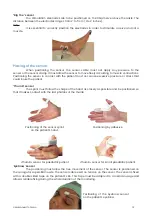
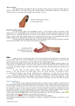
‘Big Toe’ sensor


The positioning must allow the free movement of the sensor. The sensor cable exert no 

tension on the sensor. The sensor is fixed with a medical tape to the patient’s big toe. It is essential to 

note that the toe and ankle of the patient must be free to move.

Position of the ‘big toe’ sensor 

on the patient’s toe

Single-use hand sensor


The user will position the disposable sensor on the patient’s hand according to the  

instructions on the packaging. Ensure that the sensor does not exert excessive pressure on the  

patient’s  skin  or  impede  the  blood  circulation  of  the  fingers  (avoid  excessive  tightening  of  the 


fingers, hand or any other patient limbs by the adhesives of the sensor). The integrated electrodes 

will be positioned on the path of the ulnar nerve at the wrist area inside the arm.


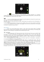
After positioning the disposable sensor on the patient’s hand, the sensor will be connected 

to the ToFscan cable (TOF-CS1) itself connected to the ToFscan.

Positioning of the 

disposable hand sensor 

and its electrodes

Notes:


While the device is being operated, the user should check that the sensor must keep the 

same position as the one from the initial set-up. The same applies for the patient’s arm, leg or head 

which should not change position for the duration of the monitoring process.

If the ‘Thumb’ sensor does not fit nicely the hand, it can be fixed with medical adhesive tape to be 

maintained in an ideal position. The user can immobilize the last three fingers with an adhesive strap 

to improve the thumb range of motion and obtain more precise measure during the monitoring of 

the thumb.


In the case of the thumb sensor, check that the splint part of the 


sensor  or  the  ring  around  the  index  finger  does  not  cause  pressure  or  excessive  stress, 

an adhesive positioning (see image «Positioning by adhesive») can then be put in place.  


After a certain period of use of the sensor, a slight mark or redness of the skin in the 

contact area with the sensor may appear. This mark or redness is due to the presence of the 

sensor in contact with the skin. This must remain limited, harmless and not look like an injury. 

Skin impedance


The ToFscan is an electrical stimulator with a constant current. Therefore, irrespective of 

skin impedance it will stimulate the patient with an identical current. It will function in this way so long 

as the needed voltage is below 300 V. Because of this limit you need to have a good skin impedance. 

For example, to get a 60 mA current through a resistive charge the maximum impedance should 

be equal to 5 Kohms. The skin impedance is more complex than a simple resistive charge and the 

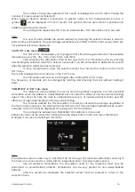
ToFscan will help you getting a good impedance with a colored electrodes symbol.  

Only the green symbol 

 allows to use in good condition the ToFscan. With yellow symbol 

the intensity of electric stimulation may be lower than expected. 

If the symbol is red 

 the ToFscan doesn’t provide electric stimulations.

If you get the screen below it is necessary to check or modify the patient’s connection to the  

electrodes.

Summary of Contents for ToFscan

Page 1: ...User Manual ToFscan 1 User Manual NeuroMuscular Transmission Monitor Version 1 8 EN DR Last Update 2021 03 05 Ref TOF IFU_EN_DR...

Page 2: ...User Manual ToFscan 2...

Page 3: ...oFscan setup 11 Cable Cable connection 11 Electrodes 11 Positioning of the electrodes 11 Placing of the sensor 12 Skin impedance 13 Connecting the cable to the ToFscan 14 Reference or REF 14 III Using...

Page 4: ...stimulation sequences in accordance to usual practice TOF PTC ATP DBS TET ST Measure the muscle response of the thumb big toe of the foot or the corrugator muscle of the eyebrow following electrical s...

Page 5: ...cturer and the competent authority of the Member State in which the user and or patient is established Warning Risk of explosion do not use the ToFscan in a flammable environment or in places where fl...

Page 6: ...such as antenna cables and external antennas should not be used within 30 cm 1 foot of any part of the ToFscan including accessories specified by the manufacturer Use of this equipment adjacent to or...

Page 7: ...cessories other than those supplied with the ToFscan The using of electrosurgery device in the same time as ToFscan can interfere the measurement and the results of it In order to prevent electrostati...

Page 8: ...e BF Applied Part Direct Current DC Manufacturing Date Temperature limit Lot code Humidity limitation Catalogue reference Atmospheric pressure limitation Curtis Straus Mark USA and Canada Prescription...

Page 9: ...n off Sound on off Check the sensor position Mandatory waiting time before the next stimulation Delete the reference value Hold down the button Stop Stop stimulation Check the electrode patient connec...

Page 10: ...of the selection screen for starting the PTC mode Battery AC power supply operation The ToFscan carries a battery enabling it to function independently on battery power for close to 1 month for more...

Page 11: ...n the adductor muscle of the thumb Thumb sensor In the case of monitoring the adductor muscle of the thumb adult or paediatric sensor the electrodes will be positioned along the ulnar nerve on the inn...

Page 12: ...e or stress that could injure the patient Thumb sensor The splint must follow the shape of the hand as closely as possible and be positioned so that it makes contact with the last phalanx of the thumb...

Page 13: ...ed in an ideal position The user can immobilize the last three fingers with an adhesive strap to improve the thumb range of motion and obtain more precise measure during the monitoring of the thumb In...

Page 14: ...se to TOF electrical stimulation when the patient is anaesthetised but not under the effect of a neuromuscular blocking agent This measurement is used to display the calculation comparisons between th...

Page 15: ...TOF sub menu After selecting the TOF menu and then the TOF sub menu the user can start a TOF stimulation or test by pressing and holding the selection wheel Prior to this he must verify that the outpu...

Page 16: ...changed after starting TOF AUTO mode The frequency of intervals can be changed by rotating and pressing the knob without holding it down REFERENCE or REF sub menu The reference mode enables the user...

Page 17: ...lied the number of responses measured is displayed with their relative amplitudes by 2 white bars The percentage of the ratio between the amplitude of the second response and the first is displayed at...

Page 18: ...re disrupted Please check the position of the sensor Principle The ATP mode is an automatic mode ATP can be stopped at any time by the user by pushing the wheel button ATP mode uses TOF and PTC stimul...

Page 19: ...ommended for eyebrow muscle monitoring ST Mode The Single Twitch stimulation is a stimulation 0 2 ms pulse duration It produces a single muscle contraction The patient s motor response is not measured...

Page 20: ...n special cases where considered appropriate by the user he she may adjust this stimulation value The user should consider the potential risks of an unsuitable stimulation current for a patient SND su...

Page 21: ...ery Battery level green yellow red The battery is above 70 of its maximum capacity The battery is between 20 and 70 of its maximum capacity The battery is below 20 of its maximum capacity The battery...

Page 22: ...to be cleaned in the same manner as the ToFscan When cleaning the cables of the ToFscan be careful not to create excessive traction on the splint that could cause premature breakage of the wires insi...

Page 23: ...hcare facility environment Voltage fluctuations Class A and flicker IEC 61000 3 3 Compliant The ToFscan can be connected to the public mains network EMC Immunity Phenomenon Basic EMC standard Professi...

Page 24: ...ion equip ment of 30cm RATED power frequency magnetic fields IEC 61000 4 8 30 A m 50 Hz or 60 Hz 30 A m 50 Hz or 60 Hz Mains power quality should be that of a typical residential commercial or hospita...

Page 25: ...mption With power supply connected 1 Watt while in use and 0 1 Watt while in sleep mode Environment Shipping and storage conditions The ToFscan and its accessories must be stored or transported under...

Page 26: ...or eyebrow Sensor length 3 meters 10FT TOF FS_B Foot Sensor length 3 meters 10FT TOF PS_B Pediatric Hand Sensor length 3 meters 10FT TOF PS2_B Small Pediatric Hand Sensor length 3 meters 10FT TOF STIC...

Page 27: ...User Manual ToFscan 27...

Page 28: ......

Reviews: