


2
Before reading this manual
This manual contains basic instructions on installing and using Digital Video Recorder, an IDIS product.
Users who are using this product for the first time, as well as users with experience using comparable products,
must read this manual carefully before use and heed to the warnings and precautions contained herein while using
the product. Safety warnings and precautions contained in this manual are intended to promote proper use of the
product and thereby prevent accidents and property damage and must be followed at all times.
Once you have read this manual, keep it at an easily accessible location for future reference.
•
The manufacturer will not be held responsible for any product damage resulting from the use of unauthorized parts and
accessories or from the user's failure to comply with the instructions contained in this manual.
• It is recommended that first-time users of Digital Video Recorder and individuals who are not familiar with its use seek
technical assistance from their retailer regarding product installation and use.
• If you need to disassemble the product for functionality expansion or repair purposes, you must contact your retailer and
seek professional assistance.
•
Both retailers and users should be aware that this product has been certified as being electromagnetically compatible for
commercial use. If you have sold or purchased this product unintentionally, please replace with a consumer version.
Safety Precautions
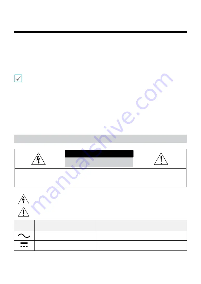
CAUTION
RISK OF ELECTRIC SHOCK
DO NOT OPEN
CAUTION
: TO REDUCE THE RISK OF ELECTRIC SHOCK,
DO NOT REMOVE COVER (OR BACK).
NO USER-SERVICEABLE PARTS INSIDE.
REFER SERVICING TO QUALIFIED SERVICE PERSONNEL.
The lightning flash with arrowhead symbol, within an equilateral triangle, is intended to alert the user to the
presence of uninsulated "dangerous voltage" within the product’s enclosure that may be of sufficient magnitude to
constitute a risk of electric shock.
The exclamation point within an equilateral triangle is intended to alert the user to the presence of important
operating and maintenance (servicing) instructions in the literature accompanying the appliance.
Symbol
Publication
Description
IEC60417, No.5032
Alternating current
IEC60417, No.5031
Direct current


