background image

Part 1 – Introduction

10

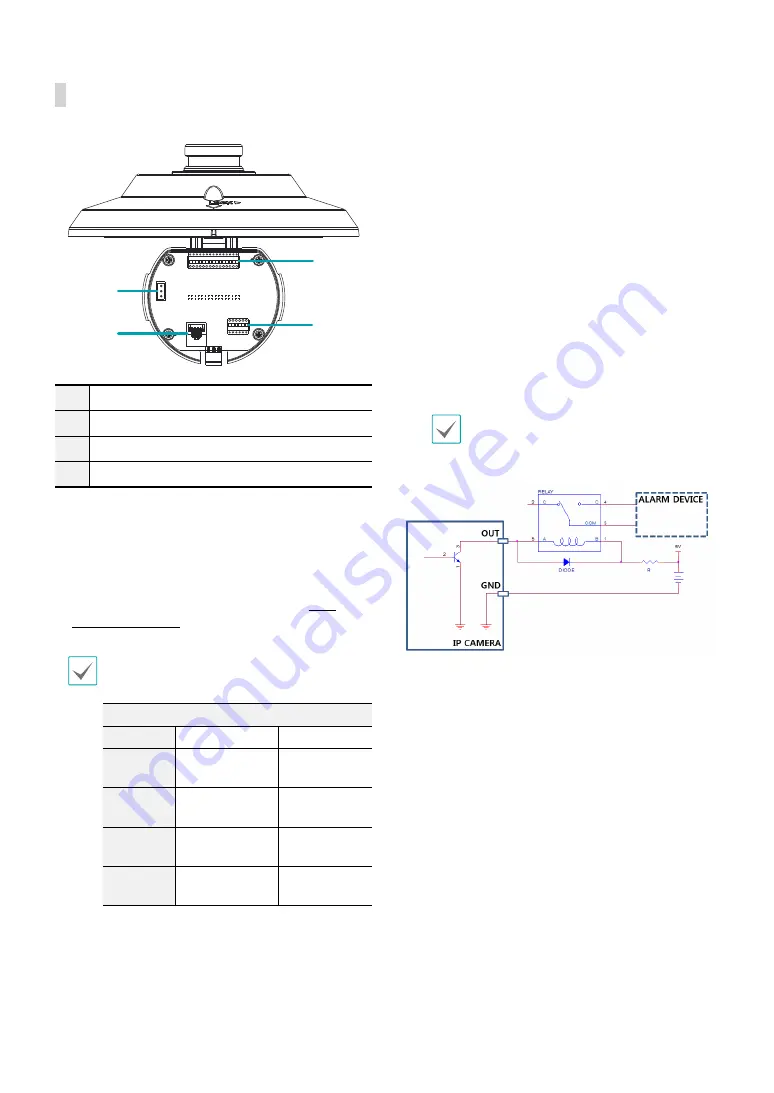
Pendant (Inner View)

1

2

3

4

1

Power

2

Network Port

3

Alarm In/Out

4

Video Out, Audio In/Out


Network Port

Connect a network cable with an RJ-45 connector to 
this port. You can configure, manage, and upgrade 
this camera and monitor its images from a remote 
computer over the network. For more information 
on network connection setup, refer to the 

INIT 

operation manual

.

The table below shows the network cable 
specifications.
<The network cable specifications>

Item

Content

Note

Connector RJ-45

Ethernet

10/100/1000 
Base

10/100/1000 
Mbps

Cable

UTP Category 
5e or higher

Maximum 
length

100m

PoE

IEEE 802.3af, 
Class 7


Alarm In/Out


ALI

:Connect an alarm-in device to this port. 

(Mechanism: Choose between an NC (Normally 
Closed) type or an NO (Normally Open) type) 


Connect a mechanical or electrical switch to the 
alarm in port and the GND (ground) connector. 
Alarm in range is 0V to 5V. In order to detect alarm 
input from an electrical switch, the signal must be 
higher than 4.3V from an NC switch or less than 
0.3V from an NO switch and must last for longer 
than 0.5 seconds.


ALO

: It is the BJT (Bipolar Junction Transistor) - 

open collector output. If the voltage and current 
exceed the specification limit (Max load: 50mA, 
Max Voltage: 30VDC), the product could be 
damaged. When connecting the device which 
exceeds the specification limit, refer to the picture 
(circuit) below.

If used with an external inductive load(e.g. relay), 
a diode must be connected in parallerl with 
the load for protection. Otherwise, the product 
could be damaged.


Audio In/Out, Video Out


A_I

: Connect an audio source to this port. (line in)


A_O

: Connect an amplifier to this port (line out). 

This device does not feature a built-in audio 
amplifier unit and therefore requires the user to 
purchase a separate speaker system with a built-in 
amplifier.


V_O, GND

: Connect the cable's signal line and 

ground line to these ports and the connector on 
its opposite end to a monitor. Use these ports 
for previewing video and not monitoring video. 
Go to Remote Setup (Video – Camera menu > 
Miscellaneous tab) and choose a video out signal. 
(NTSC or PAL)

Summary of Contents for DirectIP DC-S Series

Page 1: ...Powered by DC S Series Installation Manual DC S3883HRX DC S3583HRX...

Page 2: ...explanation about some functions may not be incorporated The manufacturer is not responsible for any problems resulting from the use thereof The information contained herein is subject to change witho...

Page 3: ...se a surge protection device 10 Overloading Do not overload wall outlets and extension cords as this can result in the risk of fire or electric shock 11 Objects and Liquids Never push objects of any k...

Page 4: ...or human health from uncontrolled waste disposal please separate this from other types of wastes and recycle it responsibly to promote the sustainable reuse of material resources Household users shou...

Page 5: ...view 9 Body 9 Pendant Inner View 10 Factory Reset 11 Installation 12 Inserting a SD Memory Card 12 Installation 12 Dimensions 14 Part 2 Camera Connection 15 With DirectIP NVR based Layout 15 With non...

Page 6: ...IDIS Web is running Supports DirectIP mode working with a DirectIP NVR that allows users to simply set up all required configurations without a PC Supports ONVIF protocol Core specification version 2...

Page 7: ...firmware and auto recovery features for improved system stability Network based integrated management of multiple network cameras Multiple event detection modes Backup storage on a microSD memory car...

Page 8: ...k inside the box to make sure all the following accessories are included External appearances and colors of the accessories may vary depending on the model Network Camera Mount Adapter Screws Allen Wr...

Page 9: ...MLC Multi Level Cell card by SanDisk or Transcend is recommended Make sure that the cover is joined properly when screwing it otherwise the IP66 level is not guaranteed To remove insert the SD memory...

Page 10: ...ch the signal must be higher than 4 3V from an NC switch or less than 0 3V from an NO switch and must last for longer than 0 5 seconds ALO It is the BJT Bipolar Junction Transistor open collector outp...

Page 11: ...ce video stuttering Ferrite Core EARTH Cable The network connector is not designed to be connected directly with cable or wire intended for outdoor use Factory Reset Only use the factory reset button...

Page 12: ...ra may fall off if the wall or ceiling is not strong enough to support its weight Install the camera in a shaded area If the camera is installed in direct sunlight it may be affected adversely 1 Make...

Page 13: ...bottom of the pendant to lower it and connect the cable 5 Assemble the pendant and the body by matching the installation direction guides Rotate the camera body clockwise to position the reference mar...

Page 14: ...Part 1 Introduction 14 Dimensions 401 1mm 15 79 20mm 242mm 9 52 43 5mm 1 71 7mm 4mm 242mm 9 52...

Page 15: ...Audio In Network 24 VAC 24 VAC Network NVR DirectIP NVR makes it easy to use cameras without extra network configurations Each camera can be controlled via the DirectIP NVR setup menu without any PC...

Page 16: ...Compact microSD Memory Card Alarm Out Sensor In Audio Out Audio In 24 VAC Control the camera over the network from software installed on a computer Ideal for using the camera over the network from a r...

Page 17: ...color appears incorrect Check the white balance settings If using the Auto option it may take some time for the white balance to be adjusted Images are blinking If the camera is pointed at the sun or...

Page 18: ...V 0 9 D 8M Wide 58 2 H 34 4 V 65 2 D Tele 1 99 H 1 13 V 2 3 D Min Illumination Color 0 175 lux 5M Color 0 0366 lux 8M B W 0 lux IR LED ON Dynamic Range 120 dB True WDR Electronic Shutter Speed Auto Ma...

Page 19: ...fe Prolonged use will damage the card s memory sectors and result in data loss or memory card failure Test the SD memory card regularly and replace it whenever necessary microSD Logo is a trademark of...

Page 20: ...Part 3 Appendix 20 External Dimensions x H 9 52 x 15 79 242mm x 401mm Weight Main Unit 16 31 lbs 7 4kg V1 1...

Page 21: ...IDIS Co Ltd For more information please visit at www idisglobal com...

Reviews: