34
©Godiva Ltd. Our policy is one of continuous development. We therefore reserve the
right to amend specifications without notice or obligation.
Foam Tank Low Level Sensor
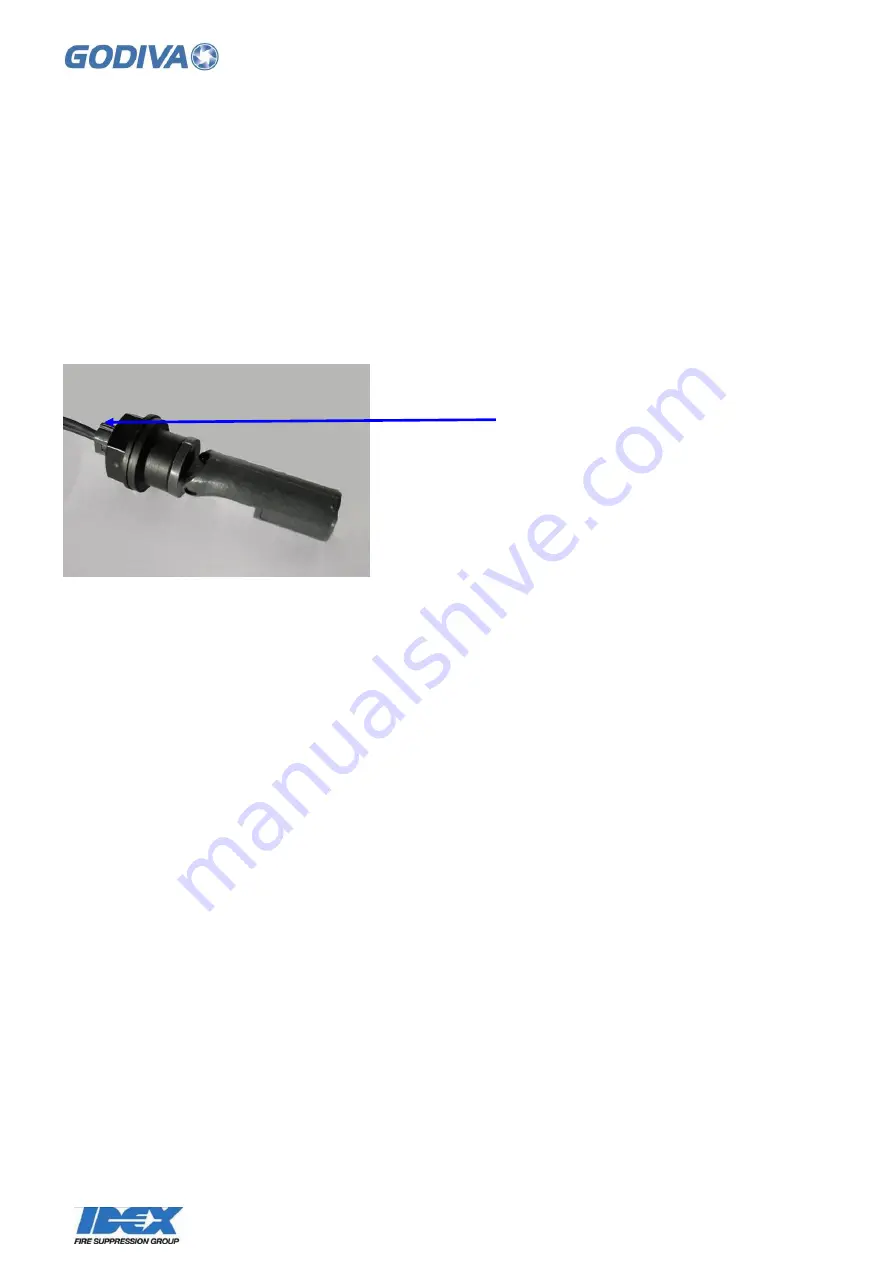
The unit is supplied with a connector for a low foam level sensor. The sensor is supplied with
the unit ready for installation (instructions supplied with the sensor).
The low foam level sensor is part of the Safety Interlock system and must be installed.
Note:
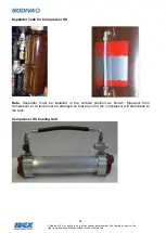
The low foam level sensor must be installed in the tank in the correct orientation. The
sensor has a raised boss on the casing and must be installed with this boss at 12 o clock
(top).
The foam tank requires a 23mm hole for secure fitting of the switch device and the maximum
allowable thickness of the tank wall material is 4mm.
The centre of the level switch should be located a minimum of 40mm above the foam
concentrate outflow to the foam pump.
Additional Installation Points
Foam Tank to Foam Pump
The foam feed line must not at any point be lower that the foam pump and be fitted with an
isolating tap for maintenance purposes. The isolating tap should be located as close to the
tank as possible. A flushing point should be fitted close to the isolating tap to ensure that the
maximum length of hose line can be flushed out. The flushing line should also be fitted with
an isolating valve.
Foam supply line I.D.
Class A
19mm minimum
Class B
25.4mm minimum
The foam tank must be located to provide a positive head of foam concentrate to the
FoamLogix unit, and the supply hose should be arranged to fall gradually from the
tank to the foam pump inlet to avoid air pockets. A tank drain valve must also be fitted.
The foam tank should be made of plastic or stainless steel, with a volume greater than the
vehicle main tank by a factor of 0.005. Alternatively, a volume of at least 25 litres may be
preferred to allow an entire drum of foam agent to be contained.
Note:
To ensure correct operation of the FoamLogix pump, all connections must be secure
and pressure tight.
Boss location

