

OFF
OFF
S2
ON
OFF
ON
bps
9600
38400
S1
Baud Rate Settings (S1 – S2 in SW3)
OFF
57600
115200
ON
ON
6.
Tighten the screws until the wire is securely fastened in the slot.
7.
If you removed the green connector in step 3, push the green
connector into the appropriate socket until it locks into place. The
connector and socket are keyed, so there is only one way to plug it in.
8.
Reconnect the system power by first connecting the AC power
connector, then connecting the standby battery connector.
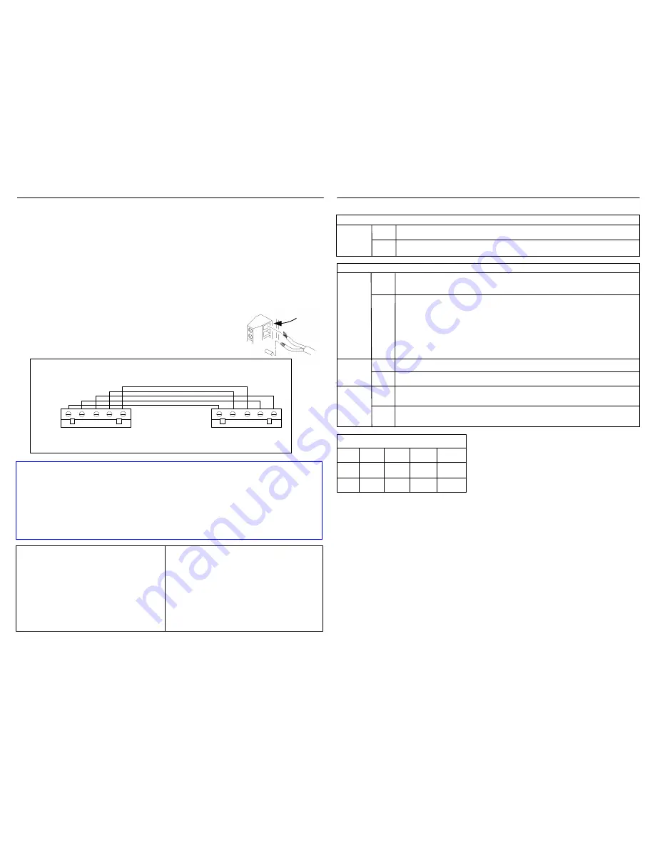
Wiring the Board
Insert wires into
green connectors
Before installing the SNIB2, you should set the required DIP switches on its three switch banks:
OFF
ON
Switch Bank 1 (SW1)
This SNIB2 is first (master) or last (termination) in the multidrop sequence.
This SNIB2 is in the middle of a multidrop sequence.
S1 - S4
Setting Up the Board
OFF
ON
Switch Bank 2 (SW2)
The SNIB2 communicates with the host PC in XNET 2 using the encryption
keys stored in memory.
Return the encryption keys to their default settings. If this switch is set when
the SNIB2 powers up or reboots after a firmware upgrade, the keys reset.
This switch can be turned off after the LED patterns begin to light. See the
SNIB2 Troubleshooting Guide
. If this is the master SNIB2, you must also
‘Reset Encryption’ on the Velocity Port settings. All downstream units must
also have their encryption keys reset. If this is a downstream unit, the master
SNIB2 automatically detects that the encryption keys have been reset.
S1
OFF
Normal operation.
This SNIB2 is
not
first in the multidrop sequence, or you have only one
controller.
S2 - S3
OFF
S4
ON
This SNIB2 is first in the sequence (master) and is connected to the host via
Ethernet or direct RS-232 connection (not dial-up). This SNIB2 controls polling.
Baud rates only apply to the SNIB2’s RS-485 and RS-232 ports. The SNIB2’s Ethernet port is used
for host-to-controller connections and runs at 10/100 BaseT speeds. All SNIBs/SNIB2s in an RS-485
multi-drop sequence must be set to the same speed, and if connected to a host PC using RS-232 direct
connection, the same speed must also be used. For example, if any SNIB2 in the sequence is set to
9600, all other SNIBs and SNIB2s (and the RS-232 host connection, if used) must be set to 9600.
If you plan to multidrop SNIBs/SNIB2s, the cable between the first (Master)
controller and the second must be wired as shown here:
RX- to TX-
RX+ to TX+
TX- to RX-
TX+ to RX+
Ground
Subsequent controllers on the same chain are wired point-to-point.
Address 1
Address 2
Master SNIB2
Subordinate SNIB2/SNIB
This controls the baud rate for the RS-485 multi-drop
line and the RS-232 connection. 57600 and 115200 bps
are only available if your RS-485 cables are made from
Cat5/Cat6 data grade wire. These speeds are not
recommended for installations using:
·
RS-232 connections to host
·
18- to 22-gauge shielded twisted-pair cable
·
NET*MUX4s
·
Mixed SNIBs and SNIB2s
Standard Cable
SNIB2 RS-485 installations with standard 18-,
20-, and 22-gauge shielded twisted-pair cable
should use 9600 or 38400 bps. Do not use
higher speeds. If you have communication
problems at 38400 bps, reduce it to 9600 bps.
Installations with NET*MUX4s are limited to
9600 bps.
Cat5 Cable
For new SNIB2-to-SNIB2 RS-485 installations,
we recommend making your cables with Cat5 or
equivalent grade cable to the appropriate 5-pin
green connectors. Pick one color wire, such as
brown, to use for Ground. Distances up to 4000
feet can be achieved with this RS-485 cabling
type. If there is no NET*MUX4 involved, you
can use 57600 or 115200 bps.
Communications become less robust as baud rates increase, wire gauge decreases, and
distances increase. Most tables in the
DIGI*TRAC Systems Design and Installation
Guide
for wire gauge and distance are based on 9600 baud. At higher baud rates,
maximum distances are decreased and minimum wire gauge is increased. It may not be
possible to implement the higher baud rates supported by the SNIB2 if you have long
wire runs or small wire gauges. Higher baud rates are also more dependent on the
number of twists per foot, so capacitance specifications must be strictly followed: total
wire run per port is not to exceed 100,000 pf per foot.
To connect RS-485 serial cables between SNIB2s:
1.
Turn all system power off by first removing the connector for the standby battery, then
disconnect the AC power connector or the power supply fuse.
2.
Punch out the knockout in the controller enclosure where you plan to route the RS-485 cable.
You can either route this wire through the same opening you’re using for controller board
connections, or knock out a new opening.
3.
Route the wires through the opening. If it makes serial wiring easier, detach each green connector
from the board as needed.
4.
Loosen the screws on each RS-485 connector plug you will be using.
5.
Remove insulation from the wire and insert the specified wires into the green connectors at the
required slots as shown to the right.
CCM and SNIB2 Firmware Upgrade Paths:
·
Upgrade the CCM firmware and physically replace a SNIB with a SNIB2: Upgrade the CCM
firmware first, then replace the SNIB with the SNIB2.
·
Upgrade the CCM firmware and either upgrade the SNIB2 firmware or physically replace a SNIB2
with a different SNIB2: It doesn’t matter which you upgrade first.
Firmware Download Rules:
·
Do not download CCM and SNIB2 firmware simultaneously on the same port.
·
Do not download CCM or SNIB2 firmware to the master SNIB2 at the same time as downstream
units on the same port. We recommend upgrading the master before upgrading downstream units.
·
Do not download firmware to more than two downstream CCMs or three downstream SNIB2s on
the same port at the same time. The firmware download time multiplies with each additional
controller downloading.
3
2
ON
Only when resetting this SNIB2 to the factory default settings.


