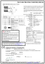
Non Contact Stand Alone Coded Safety Switches
IDEM SAFETY SWITCHES Ltd., 2 Ormside Close, Hindley Industrial Estate, Hindley Green, Wigan, WN2 4HR UK. Tel: +44 (0)1942 257070 Fax.: +44 (0)1942 257076
IDEM (USA) 4416 Technology Drive, Fremont, CA 94538 Tel:510-445-0751 Fax:1866-431-7064 email:
Web:
www.idemsafety.com
Standards:
ISO14119 IEC60947-5-3 IEC60947-5-1 UL508
ISO13849-1 EN62061 EN60204-1
Safety Classification and Reliability Data:
Power Supply
24Vdc +/-10% (Consumption 150mA max.)
Safety Output Maximum Rating
240Vac/24Vdc 3A* ac/dc
(*Max. current for QC is 2A)
Auxiliary Output Maximum Rating
24Vdc 0.5A
Dielectric Withstand
4k Vac
Insulator Resistant
100 Mohms
Recommended Setting Gap
5mm
Switching Distance
Sao 10mm Close
(Target to Time)
Sar 15mm Open
Tolerance to Misalignment
5mm in any direction from 5mm setting gap
Approach Speed
600mm/m to 1000mm/s
Body Material
PSA High Specification Polyester
MSA Stainless Steel 316
Temperature
-25C/45C
Shock Resistance
IEC 68-2-27 11ms 30g
Vibration Resistance
IEC 68-2-6 10-55Hz 1mm
Enclosure Protection
PSA: IP67 MSA: IP69K/IP67
Cable Type
PVC 10 core 7mm OD
Mounting Bolts
2 x M4
Quick Connect (QC)
Flying Lead 250mm
M12 8 way Male Plug
(Pin view from switch)
Flying
Lead
Colours
Circuit
2
Red
24Vdc
24Vdc +/- 10%
3
Blue
Supply 0Vdc
1
White
Safety Output 1 (Force guided relay)
AC15 240Vac 3A*
DC13 24Vdc 3A*
7
Black
Safety Output 1 (Force guided relay)
4
Yellow
Safety Output 2
AC15 240Vac 3A*
DC13 24Vdc 3A*
6
Green
Safety Output 2
8
Brown
Reset/Check Circuit – Output
Not Used
Orange
Reset/Check Circuit – Manual start
5
Pink
Reset/Check Circuit – Auto start
Not Used
Grey
Auxiliary Feed
Elec24Vdc 0.5A
Safety Integrity Level
SIL3
PFH (1/h)
3.95E-10
Corresponds to 4.0% of SIL3
PFD
3.46E-05
Corresponds to 3.5% of SIL3
Proof Test Interval T
1
20a
Performance Level
E
Category
Cat4
MTTF
d
446a
Diagnostic Coverage DC
99% (high)
Doc: 102545
June 2016
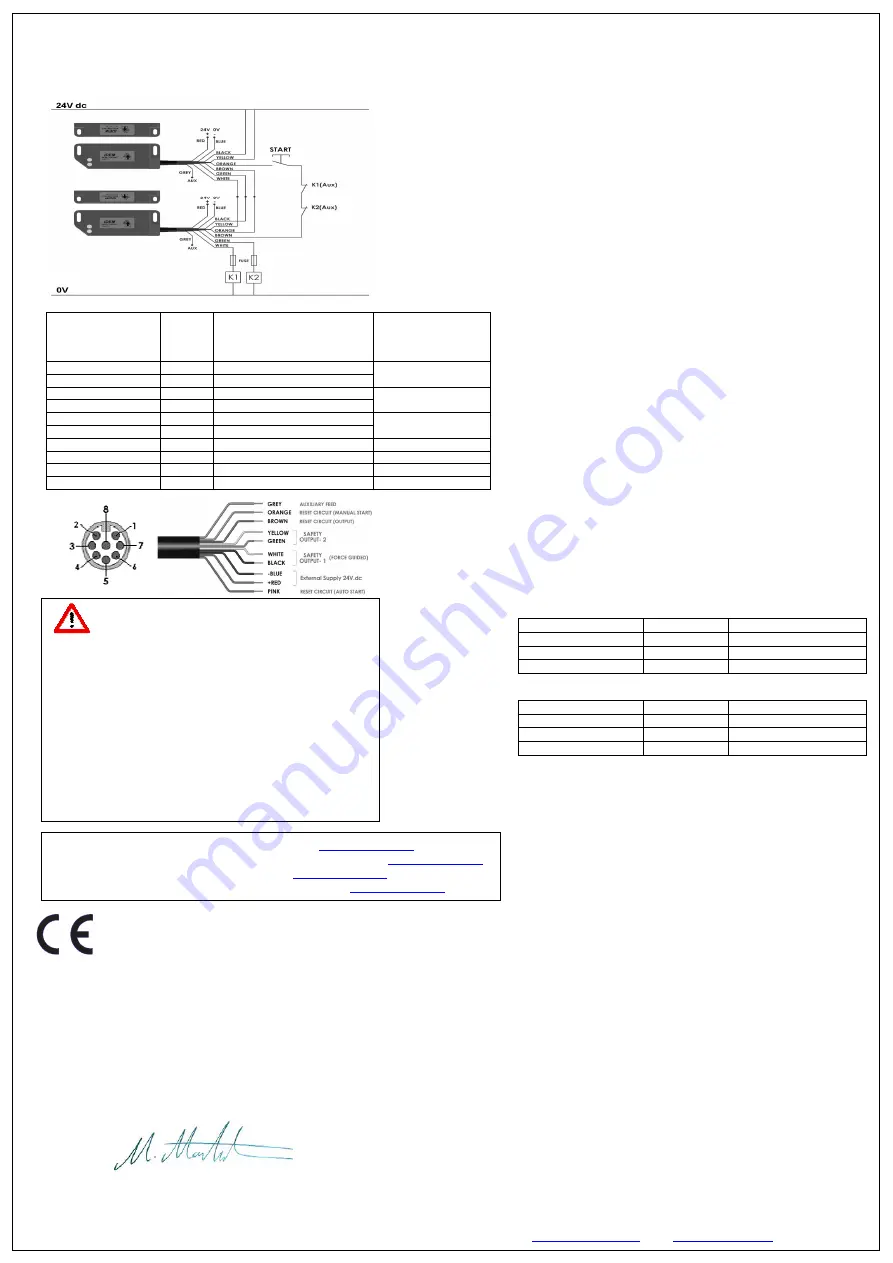
CONNECTION EXAMPLE: Switches in series PLe Cat.4
Two switches connected in series to give dual circuit safety outputs to machine contactors.
Safety Circuit 1 (Black/White) utilises internally checked force guided relay contacts and is
connected in series with the corresponding Safety Circuit 2 (Yellow/Green) of the next
switch.
Allows minimal wiring and higher current switching to K1 and K2 contactors.
A manual start and contactor feedback check is achieved by connecting K1(Aux) and
K2(Aux) feedback contacts and momentary start button through the orange and brown
feedback check.
SAFETY PRECAUTIONS:
1. Installation and commissioning of the device must be performed
only
by authorised personnel.
2. Observe the country specific regulations when installing the device.
3. The wiring of the device must comply with the instructions in this user
information - otherwise there is a risk that the safety function will be lost.
4. External fusing of the safety contacts (a slow blow or 6A quick action
must be provided).
5. All relevant safety regulations and standards are to be observed.
6. The overall concept of the control system in which the device is
incorporated must be validated by the user.
7. Failure to observe the safety regulations can result in death, serious
injury and serious damage.
8. Always use Safety Output 1.
To request this data sheet in other languages please contact
.
Um dieses Datenblatt in Deutscher Sprache wenden Sie sich bitte anfordern
.
Pour obtenir cette fiche en Français, veuillez contacter
.
Para solicitar esta hoja de datos en Español, por favor contacto con
.
EC/EU Declaration of Conformity
MANUFACTURER:
IDEM SAFETY SWITCHES LIMITED
Hindley Industrial Estate, Hindley Green, Wigan, Lancashire WN2 4HR, United Kingdom
THE LISTED DEVICES CONFORM TO THE ESSENTIAL HEALTH AND SAFETY REQUIREMENTS OF THE FOLLOWING EUROPEAN DIRECTIVES
AND STANDARDS:
Machinery Directive
(2006/42/EC)
EMC Directive
(2014/30/EU)
DEVICES: NON CONTACT SAFETY SWITCHES:
PSA MSA Standalone Coded Safety Switches
STANDARDS (plus amendments):
EN 60947-5-3
2013
EN ISO 13849-1:
2008 + AC: 2010 + AC: 2013
M.Mohtasham Managing Director
1
st
May 2013
Characteristic Data according to IEC62061 (used as a sub system)
Characteristic Data according to EN ISO13849-1
The calculation of the above values is based on the following assumptions:
Number of operating days per year:
d
op
= 365d
Number of operating hours per day:
h
op
= 24h
Number of operating cycles per day:
n
cyc
= 1/d
B10
d
= 150,000 AC1 Load 3A
= 2,000,000 AC1 Load 0.5A
When the product is used deviant from these assumptions (different load,
operating frequency, etc.) the values have to be adjusted accordingly.
*Max. current for Quick Connect is 2A.
Information with regard to UL 508:
Type 1 Enclosures.
Maximum Temperature 45C
Maximum Output 24Vdc 3A
Use Class 2 Supply or equivalent


