background image

OI T

ouchscreens

PLCs

Automation Software

Power Supplies

Sensors

Communication

Barriers

SA1E

Sensors

172 


www.IDEC.com

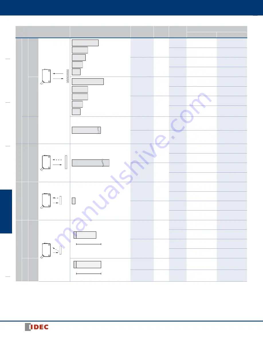
Photoelectric Switches

Sensing Method

Sensing Range

Connection

Cable 

Length

Operation 

Mode

Part No. 

NPN Output

PNP Output

Polarlized Retroflective

Red LED

w/Sensitivity Adjustment

(Note)

Note: Maintain at least the distance 

shown in the ( ) between the SA1E 

photoelectric switch and reflector. 

Reflectors are not sup plied and 

must be ordered separately.

See the characteristics on 

page 179.

2.5m (100 mm)

When using IAC-R5/R8

1.5m (100 mm)

When using IAC-R6

1.3m (150 mm)

When using IAC-RS2

1.0m (150 mm)

When using IAC-RS1

0.8m (100 mm)

When using IAC-R5/R8

Cable

2m

Light ON

SA1E-PN1-2M

SA1E-PP1-2M

Dark ON

SA1E-PN2-2M

SA1E-PP2-2M

Connector

Light ON

SA1E-PN1C

SA1E-PP1C

Dark ON

SA1E-PN2C

SA1E-PP2C

w/o Sensitivity Adjustment

3.0m (100 mm)

When using IAC-R5/R8

2.0m (100 mm)

When using IAC-R6

1.4m (150 mm)

When using IAC-RS2

1.1m (150 mm)

When using IAC-RS1

1.0m (100 mm)

When using IAC-R7

Cable

2m

Light ON

SA1E-PN1-NA-2M

SA1E-PP1-NA-2M

Dark ON

SA1E-PN2-NA-2M

SA1E-PP2-NA-2M

Connector

Light ON

SA1E-PN1C-NA

SA1E-PP1C-NA

Dark ON

SA1E-PN2C-NA

SA1E-PP2C-NA

Class 1 Laser

w/Sensistivity  Adjustment

10m

Cable

2m

Light ON/

Dark ON

SA1E-LPN3-2M

SA1E-LPP3-2M

Connector

Light ON/

Dark ON

SA1E-LPN3C

SA1E-LPP3C

Diffuse-reflective

Infrared LED

w/Sensitivity Adjustment

700 mm

Cable

2m

Light ON

SA1E-DN1-2M

SA1E-DP1-2M

Dark ON

SA1E-DN2-2M

SA1E-DP2-2M

Connector

Light ON

SA1E-DN1C

SA1E-DP1C

Dark ON

SA1E-DN2C

SA1E-DP2C

Small-beam Reflective

Red LED

w/Sensitivity Adjustment

50 to 150 mm

Cable

2m

Light ON

SA1E-NN1-2M

SA1E-NP1-2M

Dark ON

SA1E-NN2-2M

SA1E-NP2-2M

Connector

Light ON

SA1E-NN1C

SA1E-NP1C

Dark ON

SA1E-NN2C

SA1E-NP2C

Background Suppression

Red LED

w/Sensing Range  

Adjustment

20 to 200 mm

Adjustable Sensing Range

20 to 200 mm

Cable

2m

Light ON

SA1E-BN1-2M

SA1E-BP1-2M

Dark ON

SA1E-BN2-2M

SA1E-BP2-2M

Connector

Light ON

SA1E-BN1C

SA1E-BP1C

Dark ON

SA1E-BN2C

SA1E-BP2C

Class 1 Laser

w/Sensitivity  Adjustment

20 to 300 mm

Adjustable Sensing Range

20 to 300 mm

Cable

2m

Light ON/

Dark ON

SA1E-LBN3-2M

SA1E-LBP3-2M

Connector

Light ON/

Dark ON

SA1E-LBN3C

SA1E-LBP3C

Summary of Contents for SA1E Series

Page 1: ...ir blower mounting block for installing an air blower to clean the lens sur face Ideal to maintain a clean lens surface and sensor performance UL Listed and CE marked IP67 Part Numbers Photoelectric Switches Sensing Method Sensing Range Connection Cable Length Operation Mode Part No NPN Output PNP Output Through beam Infrared LED w Sensitivity Adjustment 10m Cable 2m Light ON SA1E TN1 2M SA1E TP1 ...

Page 2: ... IAC R7 Cable 2m Light ON SA1E PN1 NA 2M SA1E PP1 NA 2M Dark ON SA1E PN2 NA 2M SA1E PP2 NA 2M Connector Light ON SA1E PN1C NA SA1E PP1C NA Dark ON SA1E PN2C NA SA1E PP2C NA Class 1 Laser w Sensistivity Adjustment 10m Cable 2m Light ON Dark ON SA1E LPN3 2M SA1E LPP3 2M Connector Light ON Dark ON SA1E LPN3C SA1E LPP3C Diffuse reflective Infrared LED w Sensitivity Adjustment 700 mm Cable 2m Light ON ...

Page 3: ...2m Light ON SA1E GN1 2M SA1E GP1 2M Dark ON SA1E GN2 2M SA1E GP2 2M Connector Light ON SA1E GN1C SA1E GP1C Dark ON SA1E GN2C SA1E GP2C Coaxial Polarized Retro reflective Red LED w Sensitivity Adjustment Note Reflector is not supplied and must be ordered separately See characteris tics diagrams on page 179 2 0m when using IAC R9 1 0m 100 mm when using IAC R10 1 0m 100 mm when using IAC R11 Cable 2m...

Page 4: ...nt Adjustable using a potentiometer approx 260 Through beam type and polarized retroreflective type are also available without sensitivity adjustment Laser models 2 turn adjustment Adjustable using a potentiometer approx 260 Adjustable using a potentiometer approx 240 Sensing Range Adjustment 6 turn control knob Light Source Element Infrared LED Red LED Red laser diode Red LED Red laser diode Infr...

Page 5: ...tric switch and reflector IAC R5 R6 R7 R8 100 mm IAC RS1 RS2 150 mm The detection distance cannot be guaranteed if the reflector is deformed or the tape type reflector is applied on uneven surface 2 Cable length 1m 50g when the cable length is 2m 55g for laser models 110g when the cable length is 5m 120g for laser models 3 Cable length 1m 55g when the cable length is 2m 120g when the cable length ...

Page 6: ... 4 6 5 Round Slit SA9Z S12 SA9Z S13 SA9Z S14 øA 4 4 8 2 32 1 6 1 0 3 Material Stainless Steel Cable Model Through beam 2 M3 3 4 19 5 1 2 25 4 31 5 13 4 9 0 2 9 10 8 8 8 Stable LED green 2 Operation LED yellow 1 Sensitivity Control 2 4 6 5 10 8 7 1 Note 3 12 7 17 4 Receiver Projector 17 4 10 8 6 5 4 0 17 1 Projector or Receiver Polarized retroreflective Diffuse reflective Small beam reflective Conv...

Page 7: ...ø5 2 14 5 11 0 2 9 10 8 0 9 31 5 25 4 2 M3 coaxial 19 5 3 4 ø 3 5 Projector Receiver Sensitivity Control 1 Stable LED is not provided on the coaxial polarized retro reflective type Cable Model Laser Through beam Polarized Retroreflective Background Suppression Operation LED yellow Note 2 Operation Mode Switch Note 1 Operation LED green Note 1 Sensing Range Control BGS Sensitivity Control except BG...

Page 8: ...ugh beam projector 3 5 2 mm for polarized retroreflective type 4 No sensitivity control is installed on the type without sensitivity adjustment Polarized retroreflective Diffuse reflective Small beam reflective Convergent reflective Connector Model Background Suppression BGS M8 x 1 Note 1 Operation LED Sensing Range Control 6 turns 2 M3 Receiver Projector Yellow 19 5 3 4 2 9 11 0 7 5 31 5 25 4 0 9...

Page 9: ...nsing Distance m Sensing Distance X m Sensing Distance X m Excess Gain With vertical slit Excess Gain With horizontal slit Excess Gain With round slit Excess Gain 1 10 100 0 1 2 3 4 5 6 7 8 1 0 mm slits on both sides 2 0 mm slits on both sides 0 5 mm slits on both sides Excess Gain 1 10 100 0 1 2 3 4 5 6 7 2 0 mm slits on both sides 1 0 mm slits on both sides 0 5 mm slits on both sides Excess Gain...

Page 10: ... SA1E T NA Infrared LED w o sensitivity adjustment Excess Gain Without slit Lateral Displacement Without slit Angle Without slit Excess Gain 100 10 1 0 5 10 15 20 25 30 Lateral Displacement Y mm 1000 800 600 400 200 0 200 400 600 800 1000 0 5 10 15 20 X Y Reflector Angle 80 40 60 20 0 20 40 80 60 0 5 10 15 20 X X θ Operation Level Sensing Distance m Sensing Distance X m Sensing Distance X m Excess...

Page 11: ...on receiver Slits on both sides X Y Lateral Displacement Y mm 0 50 100 150 200 50 100 150 200 0 1 2 3 4 5 6 One slit on receiver Slits on both sides X Y Sensing Distance m Sensing Distance X m Sensing Distance X m 2 1 Polarized Retroreflective SA1E P Red LED w sensitivity adjustment Excess Gain Lateral Displacement Angle when using IAC R5 R8 Excess Gain 100 10 1 0 1 2 3 4 5 IAC R6 IAC R5 8 IAC RS1...

Page 12: ...t Excess Gain Lateral Displacement Object Size vs Sensing Distance Excess Gain White Paper Black Paper 10 5 0 5 10 0 25 50 75 100 X Y Object 200 200 mm mat paper Lateral Displacement Y mm White Paper Black Paper 10 5 0 5 10 0 50 100 150 200 X Y Object 200 200 mm mat paper Sensing Distance X mm 0 2 4 6 8 10 12 14 16 18 0 50 100 150 200 250 Sensing Distance mm Sensing Distance X mm Sensing Distance ...

Page 13: ...PC Board green The graph on the left shows the sensing distances for different colors and materials and can be used as a reference when setting the distance Because sensing distance depends on the object s size and surface condition provide a sufficient distance Note that sensing may be affected by reflective object behind the sensing object Referring to the graph on the left provide a suffi cient...

Page 14: ... Light ON Through beam Fasten the receiver temporarily Place the projector to face the receiver Move the projector up down right and left to find the range where the operation LED turns on Fasten the projector in the middle of the range Next move the receiver up down right and left in the same manner and fasten in the middle of the range where the operation LED turns on Make sure that stable LED t...

Page 15: ...A Turn the control counter clockwise to the mini mum Then turn clock wise until the operation LED turns on turns off with dark ON type point A 2 A B At interruption status turn the control clock wise from point A until the operation LED turns on turns off with dark ON type point B If the operation LED does not turn on turn off with dark ON type even though the control has reached the maxi mum set ...

Page 16: ...e the protection degree cannot be maintained Installing the Reflector Use M4 mounting screws for the IAC R5 reflector and M5 mount ing screws for the IAC R6 reflector Tighten the mounting screws to a tightening torque of 0 5 N m maximum Mounting screws are not supplied with the switch Use the M3 self tapping screw flat washer and spring washer to tighten the IAC R7 reflector to a torque of 0 5 to ...

Page 17: ...tor mounting bracket IAC L3 photo not available Reflector mounting bracket IAC L5 Slits Appearance Item Slit Size Use with Part Number Min Order Qty Vertical slit 0 5mm x 18mm SA1E SA9Z S06 2 1 0mm x 18mm SA9Z S07 2 0mm x 18mm SA9Z S08 Horizontal slit 0 5mm x 6 5mm SA9Z S09 1 0mm x 6 5mm SA9Z S10 2 0mm x 6 5mm SA9Z S11 Round slit ø0 5mm SA9Z S12 ø1 0mm SA9Z S13 ø2 0mm SA9Z S14 Connector Cables for...

Page 18: ... 98 SA9F DT11 No sleeve SA9F DT12 3 54 90mm sleeve SA9F DT13 1 77 45mm sleeve All three not compatible with green LED Straight Two fibers ø0 5mm 0 02 Threaded mount ø3mm M3 Detects ø0 03mm 0 0012 minimum object SA1C FK3 SA1C FK3G SA1C F 20mm 0 78 SA9F DD31 Coaxial Core ø1mm 0 04 16 fibers ø0 26mm 0 01 Threaded mount ø6mm M6 Detects ø0 03mm 0 0012 minimum object SA1C FK3 SA1C FK3G SA1C F 60mm 2 36 ...

Page 19: ...mm 5 91 14mm 0 55 SA9F TT11 No sleeve Straight fiber ø0 5mm 0 02 Threaded mount ø3mm M3 Detects ø0 15mm 0 006 minimum object SA1C FK3 SA1C FK3G SA1C F 50mm 1 97 5mm 0 2 SA9F TM21 No sleeve SA9F TM22 3 54 90mm sleeve SA9F TM23 1 77 45mm sleeve 16 fibers cluster Multicore ø0 26mm 0 010 Threaded mount ø4mm M4 Detects ø0 3mm 0 012 minimum object SA1C FK3 SA1C FK3G SA1C F 150mm 5 91 14mm 0 55 SA9F TM74...

Page 20: ... LED SA9F TS21 0 135m 5 31 SA9F TC21 0 1m 3 94 SA9F TM21 0 13m 5 12 Sensing ranges High speed red LED SA9F TS21 0 4m 5 75 SA9F TC21 0 3m 1 81 SA9F TM21 0 38m 4 96 Side view attachment to rotate axis by 90 for detection of opaque objects minimum size Ø 0 14 3 5mm SA1C F through beam fiber unit only SA9Z F12 Sensing ranges Standard speed red LED SA9F TS21 200mm 7 87 SA9F TC21 130mm 5 12 SA9F TM21 16...

Page 21: ...2 USA Canada Accessories Sensors OI Touchscreens PLCs Automation Software Power Supplies Sensors Communication Barriers Accessory Dimensions mm Mounting Bracket SA9Z K01 SA9Z K02 With Mounting Bracket With Mounting Bracket ...

Page 22: ...nting Bracket 14 8 3 4 30 25 5 7 t 1 2 32 7 7 24 25 4 3 2 Material Stainless Steel 10 8 24 8 13 4 28 4 19 5 1 6 Reflector IAC R5 IAC R6 Effective reflecting area 47 2 47 2 Material PMMA reflector ABS base 2 ø4 3 51 72 60 3 9 3 3 Effective reflecting area 30 31 Material PMMA reflector ABS base 2 ø3 6 8 3 35 3 34 3 42 3 8 25 4 21 With Mounting Bracket ...

Page 23: ...3 M3 tapping screw hole ø2 6 mm depth 7 7 mm Material PMMA reflector ABS base 12 4 2 7 3 Positioning Projection ø3 0 mm height 1 0 mm M3 tapping screw hole ø2 6 mm depth 7 7 mm 11 5 12 4 33 3 Material PMMA reflector ABS base 2 M3 tapping screw hole ø2 6 mm depth 8 6 mm 25 4 12 4 2 7 3 3 0 12 4 33 3 Material PMMA reflector ABS base Effective reflecting area 8 6 29 5 The mounting plate for reflector...

Page 24: ... 4 5 11 10 35 3 40 4 5 10 Material SPCC zinc plating 26 12 35 28 3 20 2 61 16 15 18 7 40 50 11 8 M3 0 7 holes Slit Vertical Slit SA9Z0S06 S07 S08 18 8 2 32 1 A 6 1 0 3 Material Stainless Steel Slit Part No Slight Width A SA9Z S06 0 5 mm SA9Z S07 1 0 mm SA9Z S08 2 0 mm Connector Cable connector on one end Straight SA9Z CM8K 4S Right angle SA9Z CM8K 4L ø5 2 ø9 6 32 Black White Blue Brown ø5 2 28 ø9 ...

Page 25: ...face The SA9Z A02 air blower mounting block is supplied with two mounting screws M3 20 mm sems screws one screw for plugging the air supply port M5 6 mm and one gasket for plugging the air supply port An air tube fitting M5 can be installed to either the top or side Tighten the fitting to a torque of 0 5 N m maxi mum The air tube fitting and mounting bracket are not supplied and must be ordered se...

Page 26: ...ies Sensors 212 www IDEC com Diffuse Reflective Light Fiber Optic Units con t Dimensions mm SA9F DD31 SA9F DM74 M6 P 0 75 1 0 9 1 2 ø3 2 mounting holes SA9F DM75 5 3 2 ø3 2m m m ounting holes SA9F DH21 M4 P0 7 SA9F DH22 M4 P0 7 SA9F TS21 SA9F TS23 2 mounting screws washer 2 mounting screws washer ...

Page 27: ...pplies Sensors Communication Barriers Diffuse Reflective Light Fiber Optic Units con t Dimensions mm SA9F TC21 SA9F TT11 2 mounting screws washer straight 2 mounting screws washer SA9F TM21 SA9F TM22 SA9F TM23 2 mounting screws washer 2 mounting screws washer SA9F TM74 SA9F TH21 2 ø3 2mm mounting holes ...

Reviews: