


4: B
ASIC
I
NSTRUCTIONS
4-28
FC6A S
ERIES
MICROS
MART
L
ADDER
P
ROGRAMMING
M
ANUAL
FC9Y-B1726
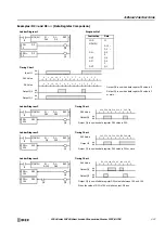
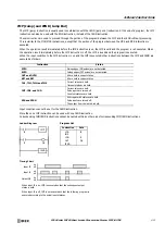
SOTU and SOTD (Single Output Up and Down)
The SOTU instruction “looks for” the transition of a given input from off to on. The SOTD instruction looks for the transition of a
given input from on to off. When this transition occurs, the desired output will turn on for the length of one scan. The SOTU or
SOTD instruction converts an input signal to a “one-shot” pulse signal.
A total of 3,072 SOTU and SOTD instructions can be used in a user program.
If operation is started while the given input is already on, the SOTU output will not turn on. The transition from off to on is what
triggers the SOTU instruction.
The SOTU or SOTD instructions cannot be used in an interrupt program.
If used, a user program execution error will result, turning on special internal relay M8004 and the ERR LED on the FC6A Series
MICROSmart. For details about the user program execution errors, see "User Program Execution Errors" on page 3-10.
When a CPU relay is defined as the SOTU or SOTD output, it may not operate if the scan time is not compatible with relay
requirements.
Note:
For restrictions on ladder programming of SOTU and SOTD instructions, see "Restriction on Ladder Programming" on page 4-33.
Note:
“T” equals one scan time (one-shot pulse).
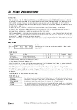
There is a special case when the SOTU and SOTD instructions are used between the MCS and MCR instructions (see "MCS and
MCR (Master Control Set and Reset)" on page 4-29). If input I2 to the SOTU instruction turns on while input I1 to the MCS
instruction is on, then the SOTU output turns on. If input I2 to the SOTD instruction turns off while input I1 is on, then the SOTD
output turns on. If input I1 turns on while input I2 is on, then the SOTU output turns on. However, if input I1 turns off while input
I2 is on, then the SOTD output does not turn on as shown below.
I0
I0
Ladder Diagram
SOTU
SOTD
Q0
Q1
LOD
SOTU
OUT
LOD
SOTD
OUT
I0
Q0
I0
Q1
Instruction
Data
Program List
Input I0
ON
OFF
Output Q0
ON
OFF
Output Q1
ON
OFF
Timing Chart
T
T
T
T
I2
I1
Ladder Diagram
Input I1
ON
OFF
SOTU Output M1
ON
OFF
SOTD Output M2
ON
OFF
Timing Chart
MCS
SOTD
MCR
No Output
No Output
I2
SOTU
Input I2
ON
OFF
M1
M2
Summary of Contents for MICROSmart FC6A Series
Page 1: ...B 1726 7 FC6A SERIES Ladder Programming Manual ...
Page 8: ...Preface 7 FC6A SERIES MICROSMART LADDER PROGRAMMING MANUAL FC9Y B1726 ...
Page 32: ...1 OPERATION BASICS 1 20 FC6A SERIES MICROSMART LADDER PROGRAMMING MANUAL FC9Y B1726 ...
Page 96: ...3 INSTRUCTIONS REFERENCE 3 18 FC6A SERIES MICROSMART LADDER PROGRAMMING MANUAL FC9Y B1726 ...
Page 130: ...4 BASIC INSTRUCTIONS 4 34 FC6A SERIES MICROSMART LADDER PROGRAMMING MANUAL FC9Y B1726 ...
Page 192: ...9 SHIFT ROTATE INSTRUCTIONS 9 12 FC6A SERIES MICROSMART LADDER PROGRAMMING MANUAL FC9Y B1726 ...
Page 272: ...12 DISPLAY INSTRUCTIONS 12 24 FC6A SERIES MICROSMART LADDER PROGRAMMING MANUAL FC9Y B1726 ...
Page 284: ...14 REFRESH INSTRUCTIONS 14 6 FC6A SERIES MICROSMART LADDER PROGRAMMING MANUAL FC9Y B1726 ...
Page 502: ...25 DATA LOG INSTRUCTIONS 25 22 FC6A SERIES MICROSMART LADDER PROGRAMMING MANUAL FC9Y B1726 ...
Page 546: ...26 SCRIPT 26 44 FC6A SERIES MICROSMART LADDER PROGRAMMING MANUAL FC9Y B1726 ...
Page 598: ...APPENDIX A 14 FC6A SERIES MICROSMART LADDER PROGRAMMING MANUAL FC9Y B1726 ...


