


53
insTallaTion
Solar Thermal -
Installation and Servicing
SOLAR CONTROLLER
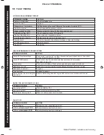
50 iDeal solar conTroller - noTes on TroublesHooTing
Warning. before opening THe fronT cover, THe poWer musT be DisconnecTeD from THe Device.
The controller was designed to be continually used for several years. Nevertheless, faults may occur. Most of the time, the fault’s
cause is not sought in the controller, rather in the peripheral system elements. The following description of a few common faults
should help the installer and the operator to isolate the fault and activate the system as quickly as possible to avoid unnecessary
costs. Naturally, not all possible faults can be listed. However, you will find the most common causes of faults that cover the
majority of the fault conditions related to the controller.
secondary condition:
possible cause
controller shows no function.
The controller’s display is blank.
No power supply, check fuse and electric mains.
secondary condition:
possible cause
The solar circuit pump connected on the controller does not run, although its switch-on conditions are met
(sun in the display).
Pump symbol rotates in the display.
Pump’s connecting line is not connected, interrupted
or fuse in the controller is burnt-out (replacement
fuses provided in the housing, see Frame 43). Only
use fuses of type 250V 4A MT.
Pump symbol does not rotate; “max“ flashes in
the storage symbol
No fault, controller deactivated the pump
because maximum storing temperature has been
reached (Details see Frame 46).
Pump symbol does not rotate; Steam symbol
flashes on the collector symbol
No fault, controller has deactivated the pump
because the collector maximum temperature
(130°C) has been exceeded. (Details see Frame 46)
Pump symbol does not rotate; Backlight display
is red; “OFF“ blinks in display
Mode switch is on manual operating position
‘Pump Off’ (Details see Frame 42).
Pump symbol does not rotate; Backlight display
flashes red and green alternately; One of the T1/
T2 temperatures displays a sensor fault.
There is a sensor fault (short circuit or
interruption); check the sensor supply lines and
its correct connection on the controller.
SYS stands for system error. That means in spite of the pump running there is a difference in temperature of more than
80 Kelvin measured between collector and storage tank. The reason for such a huge temperature difference could be a
damaged or faulty connected pump, a closed valve or air in the solar circuit. As air inside the piping cannot be overcome by
a conventional pump, circulation of the solar circuit is stopped. Check your solar-system for these sources of error to avoid
damages. You can quit the error message afterwards by pressing any key.
Temperature sensor troubleshooting. The temperature recording is performed by thermistor sensors. These sensors are
type PT1000. The resistance value changes depending on the temperature. An ohmmeter can be used to check for defective
sensors. Un-clamp the corresponding temperature sensor from the controller and then measure the resistance value. The typical
resistance values, depending on the temperature, are listed in the following table. Please observe that slight deviations are
permitted.
Temperature for Troubleshooting
Temperature
[°C] -30 -20 -10 0 10 20 30 40 50 60 70
Resistance
[.]
882 922 961 1000 1039 1078 1117 1155 1194 1232 1271
resistance values of the pT1000 Temperature sensor
Temperature
[°C] 80 90 100 110 120 130 140 150 160 170 180
Resistance
[.]
1309 1347 1385 1423 1461 1498 1536 1573 1611 1648 1685
207786-2.indd 53
16/02/2012 11:26:29


