

FAULT FINDING
F
AUL
T FINDING F
AUL
T FINDING F
AUL
T FINDING F
AUL
T FINDING F
AUL
T FINDING F
AUL
T FINDING
51
IMAX XTRA -
Installation & Servicing
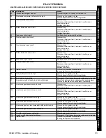
Before attempting any electrical fault finding ALWAYS carry
out the preliminary electrical system checks as detailed in
the Instructions for the British Gas Multimeter or other similar
commercially available meter.
The preliminary electrical system checks are the FIRST electrical
checks to be carried out during a fault finding procedure.
On completion of any service/fault finding task which has required
the breaking and remaking of electrical connections the following
checks MUST be repeated:
a
Earth continuity
b
Polarity
c
Resistance to earth
Detailed instructions on the replacement of faulty components
are contained in the 'Servicing' section of these Installation &
Servicing Instructions.
Before carrying out Fault Finding ensure that all external controls
are calling for heat. There should be 230V ± 10% available at the
control box connection.
ALSO CHECK BOTH OT CENTERS
ARE CORRECTLY CONFIGURED (SEE FRAME 22)
.
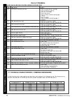
The boiler control module has replaceable fuses protecting the
230V and 24V circuits. A common reason for the 230V fuse to
blow would be if the pump connected to the boiler was drawing
more than 1 amp.
If the 230V fuse has blown, the display will be blank. Check for
short circuits and pump loads before replacing the fuse.
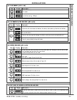
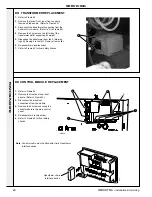
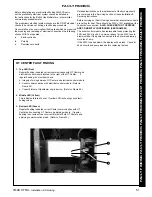
OT CENTER FAULT FINDING
1. Top LED (Red)
Regular flashing indicates correct communication with OT Center and
electrical control module located to the right of the OT Center. If
regular flashing is not evident check:
a. Integrity of wiring between OT Center and electrical control module.
b. Correct communication with electrical control module. (Refer to
Frame 42).
c. Correct fitment of Opentherm clip-in device. (Refer to Frame 66).
2. Middle LED (Yellow)
This indicates failure of boiler. If yellow LED is showing check fault
finding codes.
3. Bottom LED (Green)
Regular flashing indicates correct Center communication with OT
Center and connecting OT Center on adjoining module. If regular
flashing is not evident check correct fitment of both OT Centers and
adjoining communications lead. (Refer to Frame 23).
1
2
3


