background image

19

Concord CXS  -  

Installation & Servicing
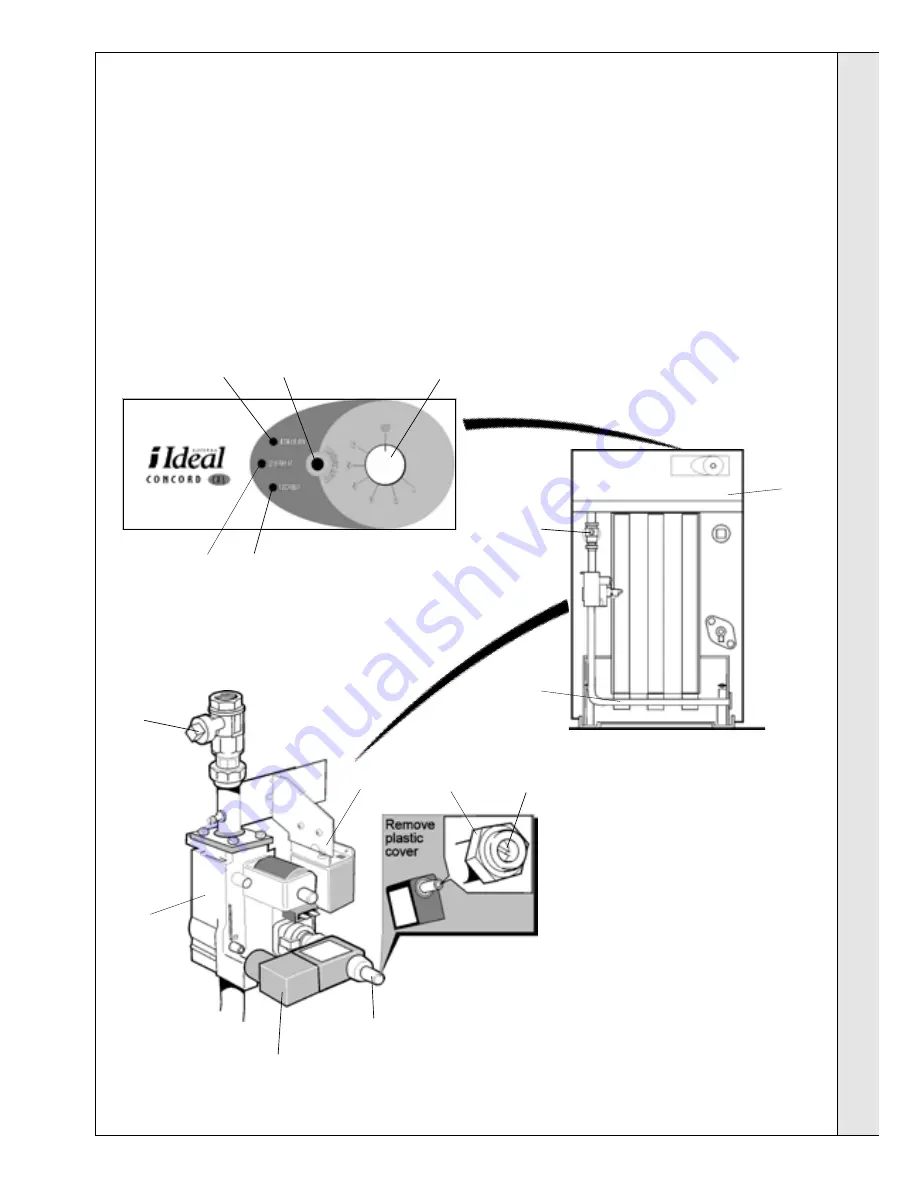
LEGEND

1.

Thermostat knob

2.

Control box

3.

Mains inlet gas cock

4.

Overheat thermostat reset button

5.

Boiler on light

6.

Lockout light

7.

Lockout reset button

8.

Manifold pressure adjuster

9.

Gas control valve

10.

High burner pressure adjuster

11.

High/low solenoid electrical plug

12.

Low burner pressure adjuster

13.

Manifold pressure test point

14.

Overheat light

1.

Check that the boiler thermostat knob (1) on the control
box  (2) is OFF.

2

. Ensure that the mains gas inlet cock (3)  is open (groove in

the square head in line with the gas pipe).

3.

Press in and release the overheat  thermostat button (4).

4.

Switch on the electrical supply to the boiler.

5.

Ensure that all system controls (time switch, system
controls etc.) are calling for heat.

6.

Turn the boiler thermostat knob (1) to position 6.

20 INITIAL LIGHTING

INSTALLATION

INST

ALLA

TION

CXS  40 - 90 boilers shown

7

. The boiler will light at Low rate and the Boiler-on light (5)

will be illuminated. If it does not light the Lockout light  (6)
will be illuminated. Press in and release the Lockout
button (7). The controls will reset and attempt to relight.

8.

The burner will remain at Low rate for about 3 minutes
before going to High rate.

9.

Check all connections for gas soundness, using leak
detection fluid.

10.

Set the boiler thermostat knob and the system controls to
the required settings.

11.

Turn off the electrical supply to the boiler.

1

5

7

6

2

3

8

11

3

10

12

13

9

3

4

2

14

Summary of Contents for Concord CXS 40

Page 1: ...tallers guide to commercial central heating boilers I N S TA L L AT I O N I D E A L I D E A L I D E A L I D E A L I D E A L M A N U A L T H E T H E T H E T H E T H E S E R V I C I N G Concord CXS 40 1...

Page 2: ...cord CXS Installation Servicing CAUTION To avoid the possibility of injury during the installation servicing or cleaning of this appliance care should be taken when handling edges of sheet steel compo...

Page 3: ...to ensure that the law is complied with The Concord CXS 40 120 range of boilers has been tested and certified by British Gas to prEN656 for use with Natural gas only Multiple boiler installations The...

Page 4: ...7 Nett kW 28 4 33 8 40 6 47 5 54 4 61 4 67 6 74 0 81 0 Btu hr x 1000 97 0 115 3 138 5 162 5 185 6 209 5 231 7 252 5 276 4 Boiler Input Gross kW 52 5 62 5 75 1 87 93 100 7 113 5 125 0 137 4 149 8 Btu...

Page 5: ...The mains voltage supply is via a terminal plug in connection at the control box OPTION KITS Remote Indication Kit This kit gives the facility of remote indication of boiler status Pressure Gauge Kit...

Page 6: ...163 0 167 213 in 2 3 4 3 1 8 3 1 8 4 5 8 4 5 8 6 1 2 6 1 2 6 5 8 8 3 8 Table 4 POSITION OF BOILER Minimum clearances required from walls or other fixed objects to allow for the free access of combusti...

Page 7: ...sitioned so that it pressurises the system being served The vertical distance between the pump s and any cold feed and expansion cistern MUST comply with the pump manufacturers requirements in order t...

Page 8: ...ot Water Boilers 60kW to 2MW BS 6880 Pt1 3 Water Supply CP342 2 Centralised Hot Water Supply Model Water Bye laws Manufacturers notes must not be taken in any way as overriding statutory obligations T...

Page 9: ...oilers and Air Heaters and the Third Edition of the 1956 Clean Air Act Memorandum should be strictly observed where applicable The chimney design should avoid the formation of excessive quantities of...

Page 10: ...nout cover 2 Collector hood 3 Middle section 4 Section alignment rings O rings 5 End section 6 Gas cock 7 Drain cock 8 NOx duct 9 Front plate 10 Burner manifold assy 11 Base plate 12 Combustion chambe...

Page 11: ...the front cross member on the packaging base 7 Remove the gas cock by unscrewing the union and screw in the handling bars into the 2 front tappings Protect the exposed inlet gas union from ingress of...

Page 12: ...ther lower rear connection using the gasket and M10 x 25mm screws and washers provided 3 Temporarily screw the 2 handling bars 2 pipe into the top tappings and manoeuvre the boiler into position 4 Com...

Page 13: ...2 Table 2 gives details of the inlet connection size and the minimum working pressures INSTALLATION INSTALLATION 12 CASING ASSEMBLY 1 Unpack the control box from its carton and release the temperatur...

Page 14: ...through the cable clips as shown Ensure the phial is correctly seated in the correct pocket opposite side to the flow connection Refer to Frame 9 Secure with the split pin provided 8 Route the temper...

Page 15: ...box is shown in Frame 15 Wiring should be in four core PVC insulated cable not less than 0 75mm2 24 0 2mm All fuses must be ASTA approved to BS 1362 The length of the conductor between the cord ancho...

Page 16: ...16 Concord CXS Installation Servicing 15 INTERNAL WIRING v violet pk pink y gyellow green or orange y yellow w white br brown r red LEGEND b blue bk black INSTALLATION INSTALLATION W4115A1020 T2...

Page 17: ...the valve for that zone When all thermostats are satisfied also when the clock period ends all relays will be off so the zone valves which were open will remain open for the pump overrun period 17 ZON...

Page 18: ...s Any leaks must be cured Replace all pressure test point screws 18 ZONES WITH SPRING RETURN MOTORISED VALVES IMPORTANT Terminal L2 may control the appropriate pump s directly provided that the total...

Page 19: ...ton 4 4 Switch on the electrical supply to the boiler 5 Ensure that all system controls time switch system controls etc are calling for heat 6 Turn the boiler thermostat knob 1 to position 6 20 INITIA...

Page 20: ...ows CXS 40 90 Boilers Refer to Frame 20 illustration Numbers in brackets in this 40 90 section also refer to Frame 20 The location of the manifold pressure adjuster 8 on the gas valve is shown in Fram...

Page 21: ...st have regular maintenance and cleaning at least annually in order to ensure reliable and efficient operation Regular attention will also prolong the life of the boiler and should preferably be perfo...

Page 22: ...ctrode shield and base fixing screws are tight 2 The electrodes are correctly positioned Refer to Frames 31 or 32 3 Reassemble in reverse order Refit the flue baffles cleanout cover NOx duct and casin...

Page 23: ...3 or 24 1 Remove the NOx duct and burner front plate as previously described in Frame 26 2 On the CXS 40 50 60 remove the screws holding the HT heat shield from the LH leg of the combustion chamber Ra...

Page 24: ...lows 1 pink 2 white 3 red Reconnect the earth terminal 5 Reassemble in reverse order ensuring that the thermostat connections are facing front before fitting the top bracket and that the capillary goe...

Page 25: ...4 Pull out the sensor plug from the PCB and remove the strain relief bush Remove the sensor and lead 5 Fit the new sensor in reverse order ensuring that the lead is routed along the casing in the clip...

Page 26: ...its contents into a commercial tip 35A CONTROL SENSOR POTENTIOMETER ASSEMBLY 1 Undo the thermostat knob retaining screw and pull off the knob 2 Remove the lower front panel 3 Undo the backnut and wash...

Page 27: ...ractice together with any relevant requirements of the local gas supplier and local authority TOOLS REQUIRED z Spanners z Torque wrench z Pozi screwdriver z Mallet ASSEMBLY The combustion chamber shou...

Page 28: ...ms a hydraulic test should be carried out at 1 1 2 times the design pressure given in Table 2 for a period of 30 minutes 12 On a pressurised system the test should be at twice the design pressure for...

Page 29: ...pump with a maximum current of 3A is connected to the boiler pump terminals pump overrun will be in operation when the demand for heat is satisfied and will continue to run for 6 minutes Frost protect...

Page 30: ...generator Replace PCB S4561B1047 YES YES 44 BOILER LIGHTS BUT GOES TO LOCKOUT NO Measure the flame current expect approximately 3 5 A Replace PCB S4561B1047 Check RH burner inlet and burner pressure...

Page 31: ...ELL VR4605AB 1019 CXS 100 120 1 111 869 29D Gas control valve plug and lead assemblies CXS 40 120 1 111 870 29E CXS 40 120 1 154 734 29F CXS 100 120 1 112 431 29G CXS 100 120 1 139 269 29H 30 Spark ge...

Page 32: ...154 867 A02 Ideal Installer Technical Helpline 01482 498376 SHORT LIST OF PARTS Key No Description Qty Product No 48 RH casing side panel white stove enamel CXS 40 1 111 650 CXS 50 60 1 111 651 CXS 70...

Reviews: