


Page 9 of 28
Quick Start Guide Stabiliti™ Series PCS
MAN-00114, Rev D
run length, number of devices on the Modbus run, type of interconnection cable, and baud rate
selected.
A maximum of one terminating resistor should be used when the Modbus interface of multiple
units are daisy chained together and connected to one master Modbus device. The optional
120 ohm Modbus terminating resistor is frequently not necessary, and may in fact interfere with
proper communications operation under some circumstances. Shorter connections typically
perform quite well without a termination resistor.
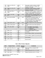
#4 - Sync/CAN
8-Pin Phoenix-style connector
Pin 1 is CAN_L
Pin 2 is CAN_H
Pin 3 is CAN isolated ground
Pin 4 is Sync RX_N
Pin 5 is Sync RX_P
Pin 6 is Sync TX_N
Pin 7 is Sync TX_P
Pin 8 is Sync isolated ground
NOTE: The CAN interface is reserved for future use.
#5 - Transfer Switch
8-Pin Phoenix-style connector
J16 pin 1 Island (24 Vdc)
J16 pin 2 Island Return (24 Vdc Return)
J16 pin 3 Island Acknowledge Return (24 Vdc Return)
J16 pin 4 Island Acknowledge (24 Vdc)
To enable voltage-forming (islanded operation), both pin 2 and pin 3 on J16 must be connected
ground, or left open. Connect to 24 Vdc to ensure the system never attemps to island while the
Facility Power Control Method is enabled.
These inputs are designed to interface with external third-party Islanding Switchgear
which allows the PCS to move between grid-following and grid-forming modes in a
seamless, blinkfree fashion to support critical loads. Detailing the Islanding Switchgear
application is beyond the scope of this initial Quick Start Guide. If not using third-party
Islanding Switchgear, leave J16 pins open.
#6 - Ethernet
8-pin RJ45 Connector
Ethernet Services
The Stabiliti
™ Series PCS supports wired Ethernet connectivity. This Ethernet connectivity


