Optia HE -
Installation & Servicing
37
SERVICING
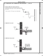
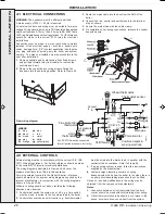
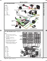
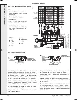
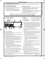
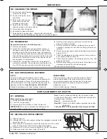
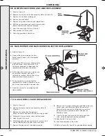
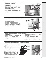
67 PILOT BURNER REPLACEMENT
1.
Refer to Frame 61.
2.
Remove the burner and air box assembly. Refer to Frame
54.
3.
Remove the electrode retaining nut and remove the pilot
shield and electrode.
4.
Unscrew the central pilot fixing screw and lift the pilot clear
of the pilot injector. The pilot injector may now be unscrewed
if required.
5.
Replace the pilot burner (injector if necessary) and retain
with the M4 screw previously removed. Ensure the copper
sealing washer is replaced when refitting the pilot injector.
6.
Replace the electrode and pilot shield, retaining
both with the electrode nut. Check the spark gap.
7.
Reassemble in reverse order.
8.
Check the operation of the boiler.
9.
The pilot is factory set to maximum and no further
adjustment is possible. Ensure there is an inlet
pressure of 20 mbar available. Also check burner
ignition and cross-lighting.
1.
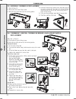
Refer to Frame 61.
2.
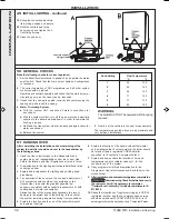
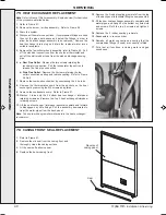
Remove the limit thermostat assembly from the
boiler flow pipe.
3.
Disconnect the electrical connectors
4.
Clip new thermostat onto flow pipe
5.
Reassemble in reverse order.
NOTE.
UNDER NO CIRCUMSTANCES REFIT THE
LIMIT THERMOSTAT ONTO THE RETURN PIPE
65 LIMIT THERMOSTAT REPLACEMENT
1.
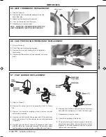
Refer to Frame 61.
2.
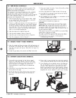
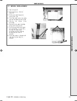
Pull off the two electrical connections.
3.
Remove the two nuts retaining the flue protection
thermostat.
4.
Replace the thermostat and re-assemble in reverse
order
66 FLUE PROTECTION THERMOSTAT REPLACEMENT
2
3
2
3
Return pipe
Flow pipe
SER
VICING
201962-6.pmd
19/02/2008, 15:10
37

