84 •
O W N E R ’ S M A N U A L
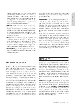
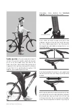
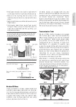
Some front disc brake equipped bicycles present
the quick-release lever on the right side, to avoid
proximity with the disc brake rotor.
If your bike has a clip-on type secondary retention
device, engage it. Holding the quick-release lever in
the OPEN position with one hand, tighten the tension
adjusting nut with your other hand until it is finger
tight against the fork dropout.
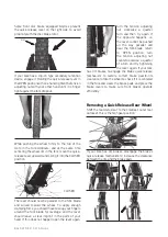
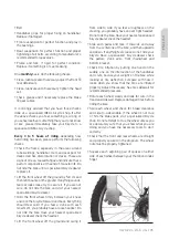
While pushing the wheel firmly to the top of the
slots in the fork dropouts, and at the same time
centering the wheel rim in the fork, move the quick-
release lever upwards and swing it into the CLOSED
position.
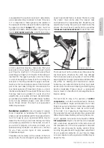
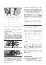
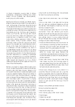
The lever should now be parallel to the fork blade
and curved toward the wheel. To apply enough
clamping force, you should have to wrap your fingers
around the fork blade for leverage, and the lever
should leave a clear imprint in the palm of your
hand. If this does not happen, open the lever again,
turn the tension adjusting
nut clockwise a quarter
turn and then try again. If
the opposite happens, i.e.
the lever cannot be pushed
all the way parallel and
near the fork blade, return
to OPEN position, turn
the tension adjusting nut
counterclockwise a quarter
of a turn and try tightening
the lever again. If your bike
has rim brakes re-engage the brake quick release
mechanism to restore correct brake pad-to-rim
clearance, rotate the wheel to check if it is centered
in the fork and clears the brake pads, and press the
brake levers to make sure front brakes operate
efficiently.
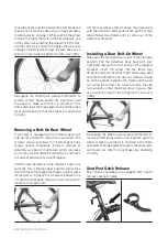
Removing a Quick Release Rear Wheel
Shift the rear derailleur to the smallest, outer rear
sprocket; this is the high gear position.
If your bike has rim brakes, disengage the brake’s
quick-release mechanism to increase the clearance
between the rim and the brake pads.
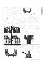
CLOSED
disc
Summary of Contents for RACE PRO 29
Page 1: ...FAHRRAD BETRIEBSANLEITUNG OWNER S MANUAL...
Page 2: ...Untitled 1 1 12 7 16 5 20...
Page 4: ...4 IDEAL IDEAL...
Page 6: ...6 30 DEAL Standover Standover Standover 5cm 10cm 7 5cm 30 32 Ideal 5 8 cm...
Page 7: ...7 minimum insertion Standover IDEAL full suspension IDEAL test drive minimum insertion...
Page 9: ...9 IDEAL Quick Release QR 5 8cm IDEAL service 23 QR QR QR QR QR QR clip on QR...
Page 10: ...10 clip on QR QR QR QR QR...
Page 11: ...11 QR clip on QR QR QR QR...
Page 12: ...12 QR QR QR QR QR QR QR...
Page 13: ...13 clip on clip on...
Page 14: ...14 QR QR QR QR IDEAL...
Page 15: ...15 v brakes...
Page 17: ...17 v brakes caliper cantilever IDEAL IDEAL IDEAL A IDEAL...
Page 18: ...18 thumb lever twist grips finger operated triggers...
Page 19: ...19 3 7 8 1 3 5 6 7 8 9 10 12 IDEAL toeclips toeclip clipless...
Page 20: ...20 clipless service IDEAL IDEAL service IDEAL...
Page 21: ...21 Schraeder Presta Schraeder Presta Presta Presta...
Page 22: ...22 SERVICE 20 service IDEAL...
Page 23: ...23 SERVICE service IDEAL IDEAL...
Page 24: ...24 IDEAL IDEAL 3 5 5 8 cm...
Page 25: ...25 2cm coaster 8 IDEAL 35 IDEAL 5...
Page 27: ...27 IDEAL O service service IDEAL...
Page 28: ...28...
Page 33: ...33 SERVICE IDEAL Dealer IDEAL service Dealer Dealer...
Page 34: ...34 SERVICE IDEAL Dealer IDEAL service Dealer Dealer...
Page 35: ...35 SERVICE IDEAL Dealer IDEAL service Dealer Dealer...
Page 36: ...36 SERVICE IDEAL Dealer IDEAL service Dealer Dealer...
Page 37: ...37 IDEAL IDEAL Fax email website Fax email website IDEAL IDEAL IDEAL IDEAL Dealer...
Page 39: ...39 IDEAL IDEAL Fax email website Fax email website IDEAL IDEAL IDEAL IDEAL Dealer...
Page 40: ...40 F A H R R A D B E T R I E B S A N L E I T U N G...
Page 76: ...76 O W N E R S M A N U A L...
Page 110: ...NOTES...
Page 111: ...Untitled 1 1 12 7 16 5 20...


