ID-AL My Video Player - VP320 and VP330 - Quick Start Guide V1.0
3 Connection of the Input Contacts
The standalone input contact of the VP320 and the VP330 or the 8 input contacts of the VP330 are used to
generate events. Triggering devices can be connected to these inputs (e.g.: push-button, presence sensor, relay,
PLC, SensoPad, IRPad, etc.). These devices must behave like open or closed contacts between an input and the
ground of the player, the activation being triggered by a closed contact by default. The activation of the standalone
input contact generates a standalone event, and the activation states (1 if activated) of the input contacts of the
VP330 are combined to form a binary code identifying the generated event:
xxxcombination
=
Input
1
+
Input
2
×
2
+
Input
3
×
4
+
Input
4
×
8
+
Input
5
×
16
+
Input
6
×
32
+
Input
7
×
64
+
Input
8
×
128
A command is assigned to each event. By default, the standalone input and the
xxx
combination on the other
inputs trigger the playback of the folders
001
and
xxx
, respectively. The setup menu allows to change these
commands. With the VP330 and up to 8 combinations (
001
,
002
,
004
,
008
,
016
,
032
,
064
,
128
), the triggering
devices can be directly connected to the inputs. Beyond, a circuit based on diodes can be used to obtain up to 255
combinations (e.g.: the board ID-AL Ext15In providing up to 15 combinations).
4 Connection of the Output Contacts
The VP330 offers 8 outputs with MOSFET switches (up to 500 mA per output) to operate power relays, motor
controllers, lights, players, and various devices. The states of the output contacts can be controlled by the
[
RESxxxxxxxx]
(applied at Start of playback) and [
REExxxxxxxx
] (applied at End of playback) folder and file tags.
xxxxxxxx
represents the activation states of the 8 outputs, from the 8
th
to the 1
st
: a
0
opens the contact, a
1
closes it,
and a
#
keeps its last state.
E.g., if
001[RES00001000][REE00000000]
is the name of the folder
001
, then the
4
th
contact is closed and all the other contacts are opened when the playback of this folder starts, and all the
contacts are opened when the playback of this folder ends.
5 First Startup
•
Make sure that the player is off (mains adapter unplugged).
•
Connect the video and audio outputs to the installation according to the needs.
•
Connect the input and output contacts according to the needs. See the chapters Connection of the Input
Contacts and Connection of the Output Contacts.
•
Connect the Ethernet network and the RS-232 serial link if needed.
•
Insert the prepared storage device. See the chapter Preparation of the Storage Device.
•
Turn the player on by plugging the mains adapter.
•
Use the setup menu to configure the player. See the chapter On-Screen User Interface.
•
The player is operational.
6 On-Screen User Interface
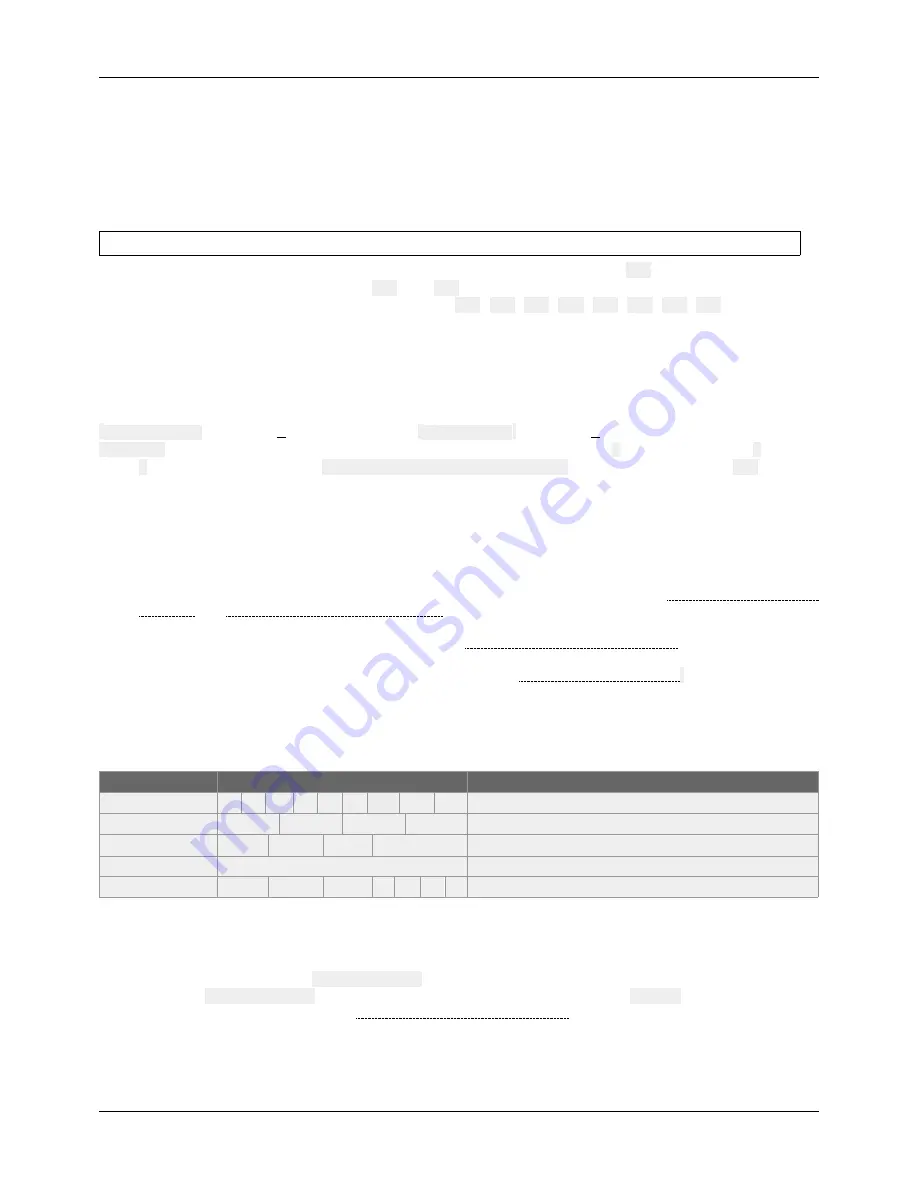
The on-screen information and menu, the clickable knob, and the infrared remote control are aimed at viewing the
player state, configuring it, and controlling the playback. The following controls are available:
Control
Remote Control Key or Front Panel Control
Description
Playback
Control the playback.
Custom
▄
▄
▄
▄
Send a configurable order.
Volume
VOL +
VOL -
Clickable knob
Change the volume.
Standby and wake up
POWER
Set the player to standby or wake it up.
Configuration
MENU
ESC
OK
Use the on-screen setup menu to configure the player.
7 Scheduler
The player can be programmed thanks to the Scheduler, according to a timetable provided on the storage device. It
manages the playback thanks to folder playback, stop and resume commands.
•
The timetable is stored in a
scheduler.tm2
file, to generate with the Scheduler software.
•
Once the
scheduler.tm2
file has been created, it must be placed in the
SYSTEM
folder of the storage
device as explained in the chapter Preparation of the Storage Device.
© 2018, Waves System - 7 impasse de La Ville en Bois, 44830 Bouaye, France - Phone: +33 (0)2 40 78 22 44 - [email protected]


