- 6 -
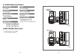
INTERFACE CONNECTOR :
Pin 1
Reserved
Reserved
Reserved
Pin
Pin 1
Pin 10
Pin 9
Pin 18
13
Pin 14 /SEND
Pin 15 Reserved
Pin 16 Reserved
Pin 17 Reserved
Pin 18 Reserved
Pin 2 INTERRUPT
Pin 3
Pin 4 GROUND
Pin 5 /DATA
Pin 6 Reserved
Pin 7 Reserved
Pin 8 Reserved
Pin 9 Reserved
Pin 10 /OUT-OF-SERVICE
Pin 11 /DEBUG DATA
Pin 12 /ACCEPT ENABLE
N.I.S.R CONNECTOR
N.I.S.R PIN LOCATIONS
18-pin mating connector pin-out assignments:
- 7 -
(7
)
C
a
b
le
Summary of Contents for N7 Series
Page 6: ...8...


