ICT ICT690-12S Instruction Manual Download Page 11


Innovative Circuit Technology Ltd. 

11 

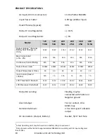
Alarm, on/off Connector: 

5 pin removable plug, cage 
clamp type 16 –24 AWG  

 
Operating Temperature Range: 

-30C to +60°C

4


Storage Temperature Range: 

-40 to +70°C 

 
Humidity: 

(Operating) 

10 – 90% (non-condensing) 


(Storage) 

5 – 95% (non-condensing) 

 
Cooling: 


Temperature controlled 
fan 

 
Regulatory Compliance: 

Designed to meet 
UL/CSA60950-1, Meets 
FCC Part 15 Class B limits 

Dimensions (inches): 


Weight: 


7.5lbs/3.4kg 


EMC Note:

 This equipment has been tested and found to comply with the limits for a Class 

B digital device, pursuant to part 15 of the FCC Rules and ICES 003. These limits are 
designed to provide reasonable protection against harmful interference in a residential 
installation. This equipment generates uses and can radiate radio frequency energy and, if 
not installed and used in accordance with the instructions, may cause harmful 
interference to radio communications. However, there is no guarantee that interference 
will not occur in a particular installation. If this equipment does cause harmful 
interference to radio or television reception, which can be determined by turning the 
equipment off and on, the user is encouraged to try to correct the interference by one or 
more of the following measures: 


Reorient or relocate the receiving antenna. 


Increase the separation between the equipment and receiver. 


Connect the equipment into an outlet on a circuit different from that to which 
the receiver is connected. 


Consult the dealer or an experienced RF technician for help. 


4


De-rate output 2% per °C above 50°C


Summary of Contents for ICT690-12S

Page 1: ...ly INSTRUCTION MANUAL 855 343 001 Models ICT690 12S ICT690 12SB ICT690 24S ICT690 24SB ICT690 48S ICT690 48SB ICT1190 12S ICT1190 12SB ICT1190 24S ICT1190 24SB ICT1190 48S ICT1190 48SB DC Power Soluti...

Page 2: ...n to ensure installation and service is done with the battery de energised Use wire and connectors rated for the maximum load current and size of battery fuse or circuit breaker Ensure battery polarit...

Page 3: ...Innovative Circuit Technology Ltd 3 Table of Contents INTRODUCTION 4 CHECK and CONFIGURE UNIT 4 INSTALLATION 6 OPERATION 7 Status Indicators and Alarms 9 PRODUCT SPECIFICATIONS 10 LIMITED WARRANTY 12...

Page 4: ...n B Remote on off control input for external control of the output Floating Form C alarm contact output supports remote monitoring of unit operation Model 1 Output Voltage V Max Output Current A Conti...

Page 5: ...r BAT terminal if required Do not ground both the load and battery as this may bypass the internal LVD circuitry AC input wiring to the Pro Series unit must be protected using an outlet with a branch...

Page 6: ...cording to the following chart LVD Setting 12V 24V 48V BAT SW1 Setting BAT SW2 Setting Disconnect V Default 11 5 23 46 x 1 Disconnect V low setting 10 5 21 42 x 0 Reconnect V Default 12 5 25 50 1 x Re...

Page 7: ...nal LVD contactor is always connected to the battery positive as shown NOTE Do not ground the battery POS terminal as this may bypass the internal LVD relay Connect the remote on off control or unit f...

Page 8: ...d by the charge current setting of SW 3 and 4 see table on page 5 while the output voltage will be determined by the battery state of charge and will rise to the output float voltage over time The bat...

Page 9: ...rs when battery voltage falls below the LVD threshold OFF OFF ON System Fault Indicates internal circuit fault Clears when all fault conditions are cleared Battery power only Enabled ON Dead or Discon...

Page 10: ...12 5A Output Power max 3 1200W 690W 1200W 690W 1200W 690W Output Noise max mVrms 30 30 30 30 40 40 Input Current max at 120Vac 12A 7A 12A 7A 12A 7A LVD Threshold V Default 11 5V 11 5V 23 0V 23 0V 46...

Page 11: ...in a residential installation This equipment generates uses and can radiate radio frequency energy and if not installed and used in accordance with the instructions may cause harmful interference to r...

Page 12: ...to ensure that ICT product manuals and promotional materials accurately describe ICT product specifications and capabilities at the time of publication However because of ongoing improvements and upda...

Reviews: