background image

USB Ranger 422 

With Premise Cabling 

1.   Plug one end of a fiber-optic patch cord (not included) into the Link 

port on the LEX unit. 

2.   Plug the other end of the patch cord into the fiber-optic information 

outlet near the host computer. 

3.   Plug one end of the second fiber-optic patch cord (not included) into 

the Link port on the REX unit. 

4.   Plug the other end of the second patch cord into the fiber-optic 

information outlet near the USB device. 

 NOTE

:

 The maximum length of the fiber-optic cable, including patch 

cords, must not exceed 500 meters. 

 NOTE

The cabling must provide a duplex connection with crossover, and 

must be terminated with MT-RJ connectors at both ends.  

Checking the Installation 

1.  Check that the Power LEDs on the LEX unit and the REX unit are 

both on. 

2.  Check that the Link LEDs on the LEX unit and the REX unit are 

both on. 

3.  Check that the Host LED on the LEX unit is on. 

4.  On the host PC, open the Device Manager applet. Expand the entry 

for Universal Serial Bus controllers by clicking the + sign. If the 
USB Ranger has been installed correctly you should find it listed as 
a Generic USB Hub. 

Connecting a USB Device 

1.  Install any software required to operate the USB device(s). Refer to 

the documentation for the device(s), as required. 

2.  Connect the USB device to the Device port on the REX unit. 
3.  Check that the Device LED on the REX unit is on.  


Summary of Contents for 422

Page 1: ...USB Ranger 422 User Guide Featuring ExtremeUSB Technology ...

Page 2: ... is likely to cause harmful interference in which case the user will be required to correct the interference at his own expense CE Statement We Icron Technologies Corporation declare under our sole responsibility that the USB Ranger to which this declaration relates is in conformity with European Standard EN 55022 A1 Class A and EN 50082 1 IEC 801 2 IEC 801 3 IEC 801 4 IC Statement This Class A di...

Page 3: ...lling the LEX unit 5 Installing the REX unit 5 Connecting the LEX unit to the REX unit 5 Checking the Installation 6 Connecting a USB Device 6 Troubleshooting 7 Specifications 9 Limited Hardware Warranty 10 Hardware Remedies 10 Limitation of Liability 10 Obtaining Warranty Service 11 Contacting Technical Support 11 ...

Page 4: ...USB Ranger 422 ii Notes ...

Page 5: ...anger for the first time you should find the following items USB Ranger User Guide LEX unit REX unit AC power adapter 2 units USB cable 2m long To complete the installation you will also require the following items that are not included with the product USB compatible computer USB device 2 strand fiber optic cable with MT RJ connectors if using surface cabling OR 2 strand fiber optic cabling with ...

Page 6: ...ology beyond the desktop With the USB Ranger 422 USB devices can be located up to 500 meters from the host computer The USB Ranger is composed of two individual units the LEX unit and the REX unit The LEX unit The LEX unit connects to the host computer using a conventional USB cable It is powered by an external AC adapter Front View Rear View 3 4 1 2 6 5 1 Power LED 2 Power connector 3 Host LED 4 ...

Page 7: ...ice LEDs 4 Device Ports USB Type A 5 Link LED 6 Link Port MT RJ Network Cabling The LEX unit and the REX unit are interconnected by up to 500 meters of fiber optic cabling Two strands of 62 5 125 multimode or 50 125 multimode fiber optic cabling are required The cabling subsystem must provide a duplex connection with crossover and must be terminated with MT RJ connectors at both ends Fiber optic c...

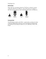
Page 8: ...he Type B connector is used to attach the USB cable to a USB device USB Type A port USB Type A connector USB Type B port USB Type B connector Compatibility The USB Ranger complies with USB 1 1 specifications governing the design of full speed USB devices However Icron Technologies Corporation does not guarantee that all full speed USB devices are compatible with the USB Ranger ...

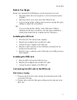
Page 9: ...nstalling the LEX unit 1 Place the LEX unit near the host computer 2 Plug the power adapter into a suitable AC outlet 3 Connect the power adapter to the LEX unit 4 Plug the Type B connector on the USB cable included into the Host port on the LEX unit 5 Plug the Type A connector on the USB cable into a USB port on the host computer Installing the REX unit 1 Place the REX unit near the USB device s ...

Page 10: ...ex connection with crossover and must be terminated with MT RJ connectors at both ends Checking the Installation 1 Check that the Power LEDs on the LEX unit and the REX unit are both on 2 Check that the Link LEDs on the LEX unit and the REX unit are both on 3 Check that the Host LED on the LEX unit is on 4 On the host PC open the Device Manager applet Expand the entry for Universal Serial Bus cont...

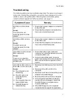
Page 11: ...al power Link LEDs on LEX unit and REX unit are off Cause There is no connection between the LEX unit and the REX unit 1 Ensure that a fiber optic cable with crossover is connected between the LEX unit and the REX unit 2 Connect a short fiber optic crossover patch cord between the LEX unit and the REX unit Recheck the operation of the system Link LED on LEX unit is on Host LED on LEX unit is off C...

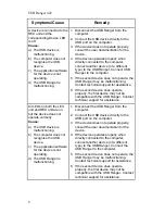
Page 12: ...te properly the first device may not be compatible with the USB Ranger Contact technical support for assistance All LEDs on both the LEX unit and REX unit are on but the device does not operate correctly Cause a The USB device is malfunctioning b The computer does not recognise the USB device c The application software for the device is not operating d The USB Ranger is malfunctioning 1 Disconnect...

Page 13: ... RJ REX unit connector upstream 1 x MT RJ REX unit connector downstream 4 x USB Type A LEX unit dimensions 114 mm x 106 mm x 38 mm 4 5 x 4 2 x 1 5 LEX unit weight 0 3 kg 0 6 lb REX unit dimensions 114 mm x 106 mm x 38 mm 4 5 x 4 2 x 1 5 REX unit weight 0 3 kg 0 6 lb Total system shipping weight 1 1 kg 2 4 lb Temperature range 4 C to 40 C Link cable not included Two strands of 62 5 125 multimode or...

Page 14: ...and fitness for a particular purpose and non infringement of third party rights with respect to the hardware Icron Technologies Corporation dealer agent or employee is authorized to make any modification extension or addition to this warranty Under no circumstances will Icron Technologies Corporation its suppliers or licensors be liable for any costs of procurement or substitute products or servic...

Page 15: ...ed to you at Icron Technologies Corporation s expense not later than thirty days after Icron Technologies Corporation receives the defective product Address the returned product to RMA Coordinator Icron Technologies Corporation 4664 Lougheed Highway Suite 275 Burnaby BC V5C 5T5 Canada Tel 604 638 3920 Contacting Technical Support If you require technical assistance send an e mail message to techsu...

Page 16: ...90 00057 A05 Icron Technologies Corporation 4664 Lougheed Highway Suite 275 Burnaby BC V5C 5T5 Canada Tel 604 638 3920 Fax 604 638 3930 www icron com ...

Reviews: