


SERVICE AND TECHNICAL SUPPORT MANUAL
Gas Furnace: N9MSB
Specifications subject to change without notice.
440 04 4412 01
25
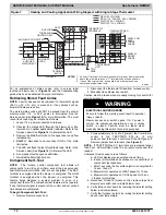
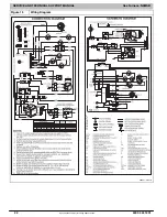
SEQUENCE OF OPERATION
NOTE
: Furnace control must be grounded for proper operation
or control will lock out. Control is grounded through
green/yellow wire routed to gas valve and manifold bracket
screw. Using the schematic diagram in
, follow the
sequence of operation through the different modes. Read and
follow the wiring diagram very carefully.
NOTE
: If a power interruption occurs during a call for heat (W),
the control will start a 90
−
second blower
−
only ON period two
seconds after power is restored, if the thermostat is still calling
for gas heating. The GREEN LED light will flash code 1+2
during the 90
−
second period, after which the LED will be
flashing a heartbeat, as long as no faults are detected. After the
90
−
second period, the furnace will respond to the thermostat
normally.
The blower door must be installed for power to be conducted
through the blower door interlock switch ILK to the furnace
control CPU, transformer TRAN, inducer motor IDM, blower
motor BLWM, hot
−
surface igniter HSI, and gas valve GV.
1.
Heating
The wall thermostat “calls for heat,” closing the R
−
to
−
W
circuit. The furnace control performs a self
−
check,
verifies the pressure switch contacts collector box
−
LPS
and housing pressure
−
HPS are open, and starts the
inducer motor IDM.
a.
Inducer Prepurge Period
−
As the inducer motor IDM
comes up to speed the collector box pressure switch
contacts LPS close to begin a 15 second prepurge
period. The inducer housing pressure switch contacts
HPS are ignored until one minute after the gas valve
closes.
b.
Igniter Warm
−
Up
−
At the end of the prepurge period,
the Hot
−
Surface igniter HSI is energized for a
17
−
second igniter warm
−
up period.
c.
Trial
−
for
−
Ignition Sequence
−
When the igniter
warm
−
up period is completed, the main gas valve relay
contacts GVR close to energize the gas valve GV, the
gas valve opens, and 24 vac power is supplied for a
field
−
installed humidifier at the HUM 24VAC terminal.
The gas valve GV permits gas flow to the burners where
it is ignited by the HSI. Five seconds after the GVR
closes, a 2
−
second flame proving period begins. The
HSI igniter will remain energized until the flame is
sensed or until the 2
−
second flame proving period
begins.
d.
Flame
−
Proving
−
When the burner flame is proved at
the flame
−
proving sensor electrode FSE, the furnace
control CPU begins the blower
−
ON delay period and
continues to hold the gas valve GV open. If the burner
flame is not proved within two seconds, the control CPU
will close the gas valve GV, and the control CPU will
repeat the ignition sequence for up to three more
Trials
−
For
−
Ignition before going to Ignition
−
Lockout.
Lockout will be reset automatically after three hours or
by momentarily interrupting 115 vac power to the
furnace, or by interrupting 24 vac power at 24VAC or
COM to the furnace control CPU (not at W, G, R, etc.).
If flame is proved when flame should not be present, the
furnace control CPU will lock out of Gas
−
Heating mode
and operate the inducer motor IDM until flame is no
longer proved.
e.
Blower
−
On Delay
−
If the burner flame is proven, the
blower motor is energized on HEAT speed 25 seconds
after the gas valve GV is energized.
Simultaneously, the electronic air cleaner terminal EAC
is energized and remains energized as long as the
blower motor BLWM is energized.
f.
Heat
−
Off Delay
−
When the thermostat is satisfied, the
R
−
to
−
W circuit is opened, de
−
energizing the gas valve
GV, stopping gas flow to the burners, and de
−
energizing
the humidifier terminal HUM 24 VAC. The inducer motor
IDM will remain energized for a 15
−
second post
−
purge
period. The blower motor BLWM and air cleaner terminal
EAC will remain energized for 90, 120, 150, or 180
seconds (depending on the heat
−
OFF delay selection).
The furnace control CPU is factory
−
set for a
120
−
second heat
−
OFF delay.
2.
Cooling Mode
The thermostat “calls for cooling.”
The thermostat closes the R
−
to
−
G
−
and
−
Y circuits. The R
−
to
−
Y
circuit starts the outdoor unit, and the furnace control
R
−
to
−
G
−
and
−
Y circuits start the furnace blower motor BLWM
on COOL speed.
The electronic air cleaner terminal EAC is energized with 115
vac when the blower motor BLWM is operating. When the
thermostat is satisfied, R
−
to
−
G
−
and
−
Y circuits are opened. The
outdoor unit will stop, and the furnace blower motor BLWM will
continue operating on the COOL speed for an additional 90
seconds. (See
) Jumper J2 can be cut to reduce the
cooling
−
)
3.
Continuous Blower Mode
When the R
−
to
−
G circuit is closed by the thermostat, the
blower motor BLWM will operate on heat speed and EAC
terminal is energized as long as the blower motor BLWM
is energized. During a call for heat, the blower BLWM will
stop during igniter warm
−
up (17 seconds), ignition (7
seconds), and blower
−
on delay (25 seconds), allowing
the furnace heat exchangers to heat up more quickly,
then restarts at the end of the blower
−
on delay period at
HEAT speed.
In heating, the furnace control CPU will continue running
the blower motor BLWM at HEAT speed after the
selected blower
−
OFF delay period is completed.
When the thermostat “calls for cooling”, the blower motor
BLWM will operate at COOL speed. When the thermostat
is satisfied, the blower motor BLWM will operate an
additional 90 seconds on COOL speed before reverting
back to continuous
−
blower speed.
When the R
−
to
−
G circuit is opened, the blower motor
BLWM will continue operating for an additional 5
seconds, if no other function requires blower motor
BLWM operation.
4.
Heat Pump Mode
Change Heat Pump to: HEAT PUMP MODE. When
installed with a heat pump, the furnace control
automatically changes the timing sequence to avoid long
blower off times during demand defrost cycles. When the
R-to-W-and-Y or R-to-W-and-Y-and-G circuits are
energized the furnace control CPU will continue to turn
on the blower motor BLWM at HEAT speed, and begin a
heating cycle. The blower motor BLWM will remain on
until the end of the prepurge period, then shut off for 24
seconds then come back on at HEAT speed. When the
W input signal disappears, the furnace control begins a
normal inducer post-purge period and the blower
switches to COOL speed after a 3 second delay. If the
R-to-W-and-Y-and-G signals disappear at the same time,
the blower motor BLWM will remain on for the selected
blower-OFF delay period. If the R-to-W-and-Y signals
disappear, leaving the G signal, the blower motor BLWM
will continue running the blower motor BLWM at HEAT
speed after the selected blower-OFF delay period is
completed.
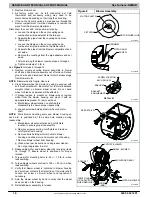
See Component Self Test
Refer to page 14 for instructions.


