background image


I-7530A RS-232/485/422 to CAN Converter User’s Manual (Version 1.2, Sep/2011) ------------- 20


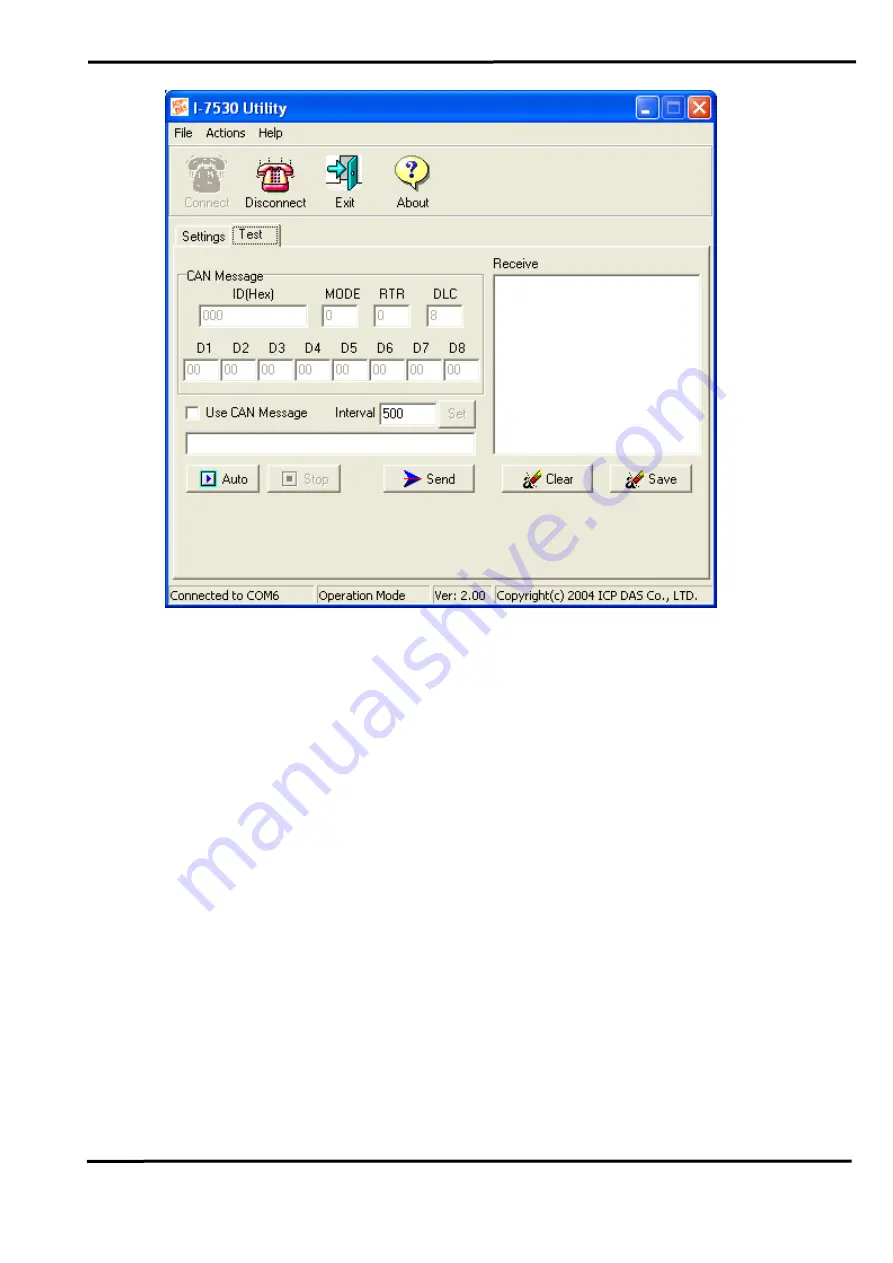
8. Users will then be able to transmit or receive CAN messages via the I-

7530A module. There are two methods for communicating with their 
CAN. The first method (check “Use CAN Message”) requires users to 
understand their CAN specifications. And input the correct data in the 
CAN message format. The second method (uncheck “Use CAN 
Message”) allows the use of the command string found in table 5 to 
transmit messages. Both methods require the user to click the “Send” 
button to transmit the information into the CAN network. The CAN 
message will then automatically be displayed in the “Receive” list box. 
Besides, user can press the “Clear” button to remove the messages on 
the list box and then the new CAN messages will be shown on the list 
box again. In addition, user can press the “Save” button to save the 
CAN messages, in the “Receive” list box, into the “Receive.txt file”. 


Summary of Contents for I-7530A

Page 1: ...liability for damages resulting from the use of this product ICP DAS reserves the right to change this manual at any time without notice The information furnished by ICP DAS is believed to be accurate...

Page 2: ...ation 11 2 7 Cable selection 12 3 Software Utility 13 3 1 How to configure the module parameters 14 3 2 How to set the Acceptance Code and Mask 18 3 3 Test I 7530A on CAN network Only for normal mode...

Page 3: ...By using I 7530A some programmable RS 232 485 422 devices such as PC I 8411 I 8431 I 8811 I 8831 embedded controllers can be the master of a CAN network Therefore they can control or monitor the CAN d...

Page 4: ...CAN 2 0A and CAN 2 0B Build in jumper to provide 120 ohm terminal resistor or not in CAN network Provide power data flow and error LED indicator for CAN and RS 232 485 422 Built in a Dual Watchdog fu...

Page 5: ...R LED for error Software Utility tool CAN bus Baud Rate configuration CAN acceptance filter configuration Setting for CAN 2 0A or 2 0B working mode Setting for I 7530A communication mode normal mode o...

Page 6: ...ation in the CAN interface site And hardware media in RS 232 interface is only adopted 3 wire connection Figure 1 Block diagram of I 7530A 2 2 Pin Assignment Table 1 RS 232 485 422 Connector CN1 Termi...

Page 7: ...2 to CAN Converter User s Manual Version 1 2 Sep 2011 7 Table 2 CAN DB9 Male Connector CN2 Terminal 2 wire CAN 1 Not Connect 2 CAN Low 3 4 5 6 Not Connect 7 CAN High 8 9 Not Connect Figure 2 Pin Assig...

Page 8: ...0A is inserted directly into a PC s COM serial port or via a cable to the Host system Figure 3 RS 232 connection The pin assignment of the CAN port on the I 7530A DB9 male defined in both the CANopen...

Page 9: ...s shown in the below figure Figure 5 Terminator resistor Therefore the I 7530A module supplies a jumper for users to connect the terminator resistor or not If users want to use this terminator resisto...

Page 10: ...will work in the configuration mode after the power for the module has been turned on In this case users can configure the communication parameters of the I 7530A module by using the I 7530 Utility to...

Page 11: ...The ERR LED is used for demonstrating an error that has occurred That is the ERR LED is normally turned off when the module works in a good condition On the other hand when the BUS OFF error indicator...

Page 12: ...nes How to decide a cable type cable length and terminator depends on the baud rate in the CAN BUS network please refer to the following table 4 Figure 9 Un shielded Twisted Pair UTP Table 4 Cable sel...

Page 13: ...web site http www icpdas com products Remote_IO can_bus i 7530A htm or get this information from the ICP DAS Fieldbus CD ROM The I 7530 Utility tool can be used to configure the operation status of th...

Page 14: ...0A module 3 The I 7530A module s ON LED will flash approximately once per second That means the I 7530A module is working in the configuration mode 4 Run the I 7530A s Utility software after connect t...

Page 15: ...e or users choose the Settings tab they can only communicate with each other by using 115200 Baud 6 Then the I 7530A configuration window will be brought out The I 7530 Utility will show the communica...

Page 16: ...tance Mask please refer to the section 3 2 2 If the Pair Connection is checked the functions of End of RS 232 command Fixed Tx CAN ID and Response with CAN ID are useful 3 When Pair Connection is chec...

Page 17: ...f the CAN and RS 232 485 422 communication parameters on the I 7530A will be set to the default values which are RS232 485 422 Baudrate 115200 Data Bit 8 Stop Bit 1 Parity None Add Checksum No Error R...

Page 18: ...ant to filter this CAN ID bit For Examples 1 If users want to get all the messages on the CAN bus the setting must be as follow In CAN 2 0A Acceptance Code Don t care Acceptance Mask 000 2 If users wa...

Page 19: ...e I 7530A module 2 Connect the I 7530A s CAN port into the CAN network which must at least have one CAN device on the network 3 Supply the 10 30 volts DC source into the I 7530A module through the pow...

Page 20: ...t The second method uncheck Use CAN Message allows the use of the command string found in table 5 to transmit messages Both methods require the user to click the Send button to transmit the informatio...

Page 21: ...o RS 232 485 422 commands by another I 7530A The following section will show each condition for different pair connection configuration Application 1 This application may be used in two general RS 232...

Page 22: ...the CAN ID is 29 bit ID Here assume users set the Fixed Tx CAN ID field of I 7530A 1 to be 0x001 0x is for hexadecimal format and CAN 2 0A is used the CAN ID displayed in above figure is 0x001 If ther...

Page 23: ...ommunication Descriptions The communication of this condition is similar with the communication of condition 1 The difference is that the I 7530A 2 of the application 1 will transfer the RS 232 comman...

Page 24: ...figure the I 7530A 1 I 7530A 2 and I 7530A 3 as follows The RS 232 configurations of these three I 7530As are decided by the RS 232 device they connect with I 7530A 3 I 7530A 2 I 7530A 1 Communication...

Page 25: ...ands 456789 the CAN message will have CAN ID 0x002 and 0x003 because of the configurations of Fixed Tx CAN ID of I 7530A 2 and I 7530A 3 Because the I 7530A 1 is set to Response with CAN ID the Device...

Page 26: ...m algorithm please refer to page 27 CR All RS 232 485 422 commands of the I 7530A Converter must end with the character CR The ASCII value is 13 The 9 commands are given in the following table More de...

Page 27: ...aracters of the sum of the command message from first character to the character before CR When calculate checksum the value of CHK is zero For example Command Reboot the I 7530A module RA CHK CR 1 Su...

Page 28: ...age 0x0 0x8 DD Input data frame value according to the data length 0x00 0xFF Response Valid command No response Invalid command Error Code CR Note It is necessary to enable the Error Response function...

Page 29: ...mote frame III 11 bits Identifier 0x000 0x7FF L Data length of a CAN message 0x0 0x 8 Response Valid command No response Invalid command Error Code CR Note It is necessary to enable the Error Response...

Page 30: ...th of a CAN message 0x0 0x8 DD Input data frame value according to the data length 0x00 0xFF Response Valid command No response Invalid command Error Code CR Note It is necessary to enable the Error R...

Page 31: ...frame IIIIIIII 29 bits Identifier 0x00000000 0x1FFFFFFF L Data length of a CAN message 0x0 0x8 Response Valid command No response Invalid command Error Code CR Note It is necessary to enable the Erro...

Page 32: ...o enable the Error Response function in the I 7530 Utility in order to receive Syntax and or communication error information at the host PC Furthermore all response results are shown in the ASCII form...

Page 33: ...eral Table 8 CAN and RS 232 485 422 FIFO overflow flag list AsciiToHex O Description Bit 3 Reserved Bit 2 Reserved Bit 1 RS 232 485 422 FIFO Overflow Bit 0 CAN FIFO Overflow Example Command S CR Recei...

Page 34: ...ommand character Response Valid Command No response This will turn the ERR LED off after the ERR LED was turned on as a result of the CAN RS 232 485 422 FIFO overflow error flag Invalid command Error...

Page 35: ...Yes Table 9 RS 232 485 422 baud rate list BB Description 00 110 bps baud rate of RS 232 485 422 01 150 bps baud rate of RS 232 485 422 02 300 bps baud rate of RS 232 485 422 03 600 bps baud rate of R...

Page 36: ...Response function in the I 7530 Utility in order to receive Syntax and or communication error information at the host PC Example Command P00B30000 CR Set the RS 232 485 422 baud rate 115 2K data bit...

Page 37: ...baud rate of CAN 4 125K baud rate of CAN 5 250K baud rate of CAN 6 500K baud rate of CAN 7 800K baud rate of CAN 8 1000K baud rate of CAN Response A valid command will write the CAN configuration bau...

Page 38: ...valid command Error Code CR Note It is necessary to enable the Error Response function in the I 7530 Utility in order to receive Syntax and or communication error information at the host PC Example Co...

Page 39: ...atch the data length of the CAN Message For example Error t001512345 CR Right t00150102030405 CR 3 Invalid checksum The checksum from the RS 232 485 422 command string does not matched with the checks...

Reviews: